10A74-4C.8 GAGE / TRANSDUCER CONNECTIONS
10A74-4C QUAD DC STRAIN GAGE TRACK-HOLD CARD
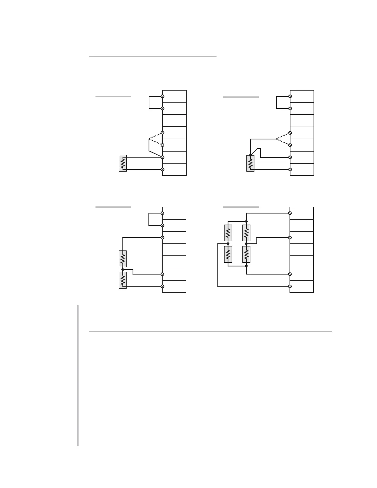
2.c FULL-BRIDGE TRANSDUCER CONNECTIONS
(WITHOUT BRIDGE COMPLETION)
In the absence of bridge-completion circuitry, the 10A74-4C's I/O CONNECTOR will
mate with Daytronic CONDITIONER CONNECTOR No. 60322, shown in Fig. 1.5 (in
Manual Section 1.E.1). Pinout for the I/O CONNECTOR is given in Table 3, above. The
required cabling is shown in Fig. 4.
Note that the main 16-wire shielded cable should contain 20- to 24-gage wires. The
length of the main cable—i.e., the distance from the 10A74-4C's rear I/O CONNECTOR
to the two “sensing points”—may be up to 500 feet. At the sensing points, the + SENSE
and –SENSE lines join the corresponding EXCITATION lines, and the main cable
divides into four separately shielded 5-wire cables (one to each full-bridge trans-
ducer). These secondary cables should contain 16- to 20-gage wires. It is important
that the distance “D” from the sensing points to each transducer be
as short as possi-
ble
; a maximum error of 0.02% could arise for every 3.5 ft. of 20-gage wire over the
distance “D,” and for every 9 ft. of 16-gage wire.
(Chn. 1, 2, 3, or 4)
(Chn. 1, 2, 3, or 4)
(Chn. 1, 2, 3, or 4)
(Chn. 1, 2, 3, or 4)
 Loading...