AA14-4F010.4 SETUP AND/OR OPERATING CONSIDERATIONS
AA14-4F010 THERMOCOUPLE CARD
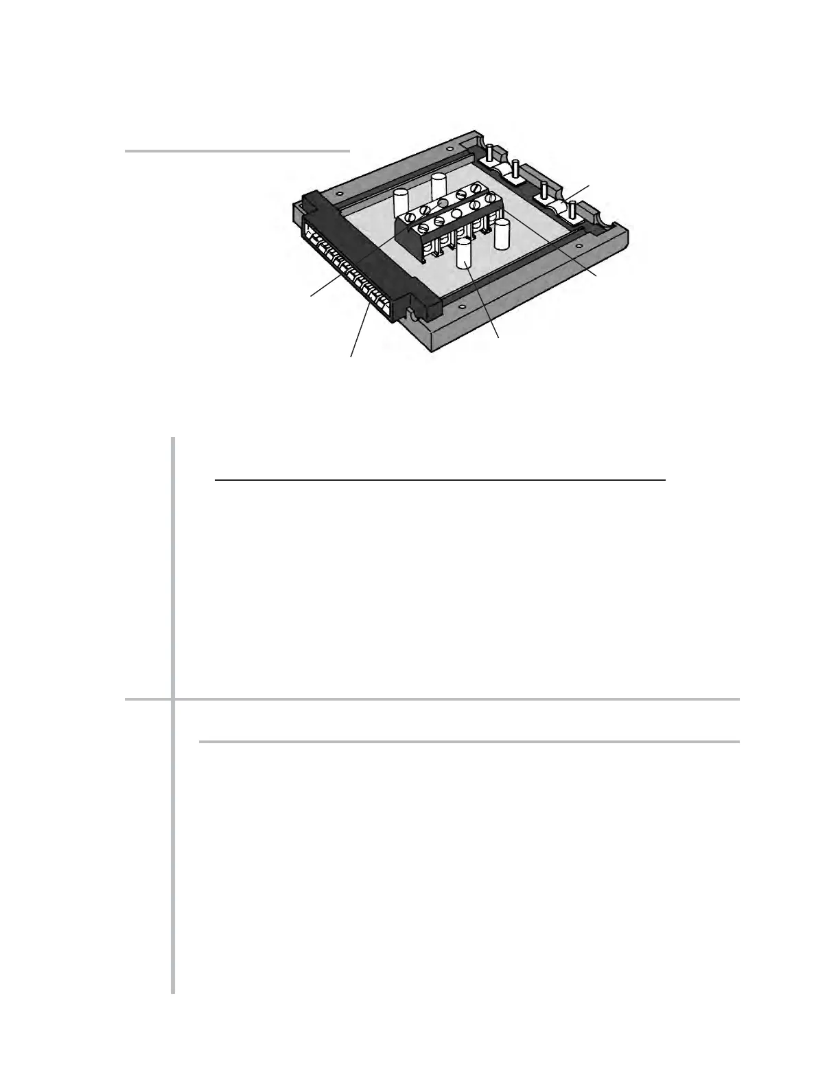
Fig. 2 Four-Channel Thermocouple
Connector Assembly (No. 60323)
Precision
Reference-Junction
Thermistor
Cable Relief Post
Cable Clamp
20-Pin Connector
(attaches to rear I/O
Connector of AA14-4F010 Card)
Screw-Terminals
(for secure connection of
thermocouple leads)
I/O Connector Conditioner Conditioner
Pin Screw Channel Line
Number Terminal Number Function
5 5(+) 3 +SIGNAL
E 5(–) 3 –SIGNAL
6 Not Committed
F Not Committed
7 7(+) 4 +SIGNAL
H 7(–) 4 –SIGNAL
8 Not Committed
J Not Committed
9 INTERNAL THERMISTOR: T1
K,L USE THERMISTOR: GROUND (COMMON)
10 ONLY THERMISTOR: T2
3 SETUP AND/OR OPERATING CONSIDERATIONS
3.a SELECTION OF “OPEN TC” POLARITY
In the event of a broken thermocouple wire or other “open TC” condition, the Model
AA14-4F010 will automatically report an indeterminate off-scale reading for the TC
channel in question. The conditioner is normally preset at the factory for
positive off-
scale “open TC” indication for each channel. However, you may easily reset any chan-
nel for
negative off-scale “open TC” indication, as follows:
1. Remove the AA14-4F010 card from its mainframe slot. For “Card Insertion and
Removal,” see Manual Section 1.B. Since the AA14-4F010 is “hot-pluggable,” you
need NOT turn off mainframe power before removing the card.
2. Refer to Fig. 5, below, and locate the OPEN TC POLARITY PROGRAMMING
JUMPER PINS on the top side of the Isolator Tile. One “minijumper” is provided
for each channel's set of three jumper pins.



 To Next Page