SETUP AND/OR OPERATING CONSIDERATIONS 10A96.3
3 SETUP AND/OR OPERATING CONSIDERATIONS
3.a SETTING FRONT-END AMPLIFIER GAIN
1. Turn OFF mainframe power and remove the 10A96 card from its mainframe slot.
For “Card Insertion and Removal,” see Manual Section 1.B.
2. Locate the FRONT-END AMPLIFIER GAIN SELECTION JUMPER PINS shown in
Fig. 2. One “minijumper” is provided for interconnecting any two vertically adja-
cent jumper pins.
3. Position the jumper as shown in Fig. 3 to set the gain to the desired gain (1, 2, 5,
10, 20, 50, or 100)
4. Do not reinstall the 10A96 card until you have set the high-pass filter gain (next
section).
3.b SETTING HIGH-PASS FILTER GAIN
1. Locate the HIGH-PASS FILTER GAIN SELECTION JUMPER PINS shown in Fig. 2.
One “minijumper” is provided for interconnecting any two vertically adjacent
jumper pins.
2. Position the jumper as shown in Fig. 4 to set the gain to set the desired gain (1, 2,
5, 10, or 20).
3. Reinsert the 10A96 card in its mainframe slot and reactivate mainframe power.
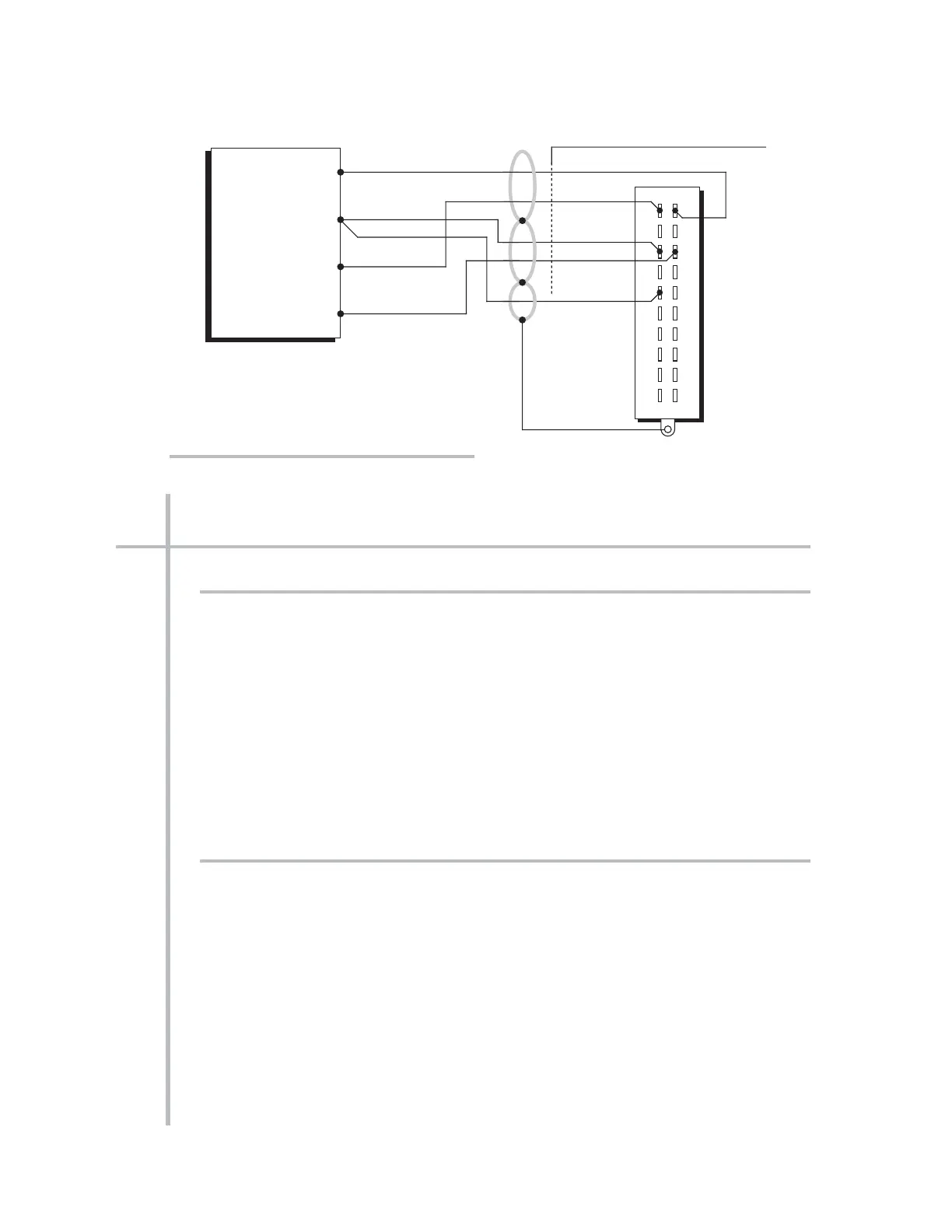
AMPLIFIED ACCELEROMETER VIBRATION CARD 10A96
CONDITIONER CONNECTOR (No. 60322)
 Loading...