Gain Stability: vs. Temperature: ±25 ppm/°C; vs. Time: ±20 ppm/month
Filter (per channel): 3-pole modified Butterworth; 3 dB down at 1.5 Hz; 60 dB down at
60 Hz
Step-Response Settling Time (Full-Scale Output):
To 1% of final value: 600 msec
To 0.1% of final value: 900 msec
To 0.02% of final value: 1 sec
Auxiliary Outputs: Filtered outputs available on mainframe wire-wrap pins
Table 1 10A43 “Type” Codes
Channel
Type Code
Dwell Angle Channel 40
Engine RPM Channel:
Maximum Expected RPM* = K x 7500 40
Maximum Expected RPM* = K x 15000 41
Maximum Expected RPM* = K x 30000 42
2 TRANSDUCER CONNECTIONS
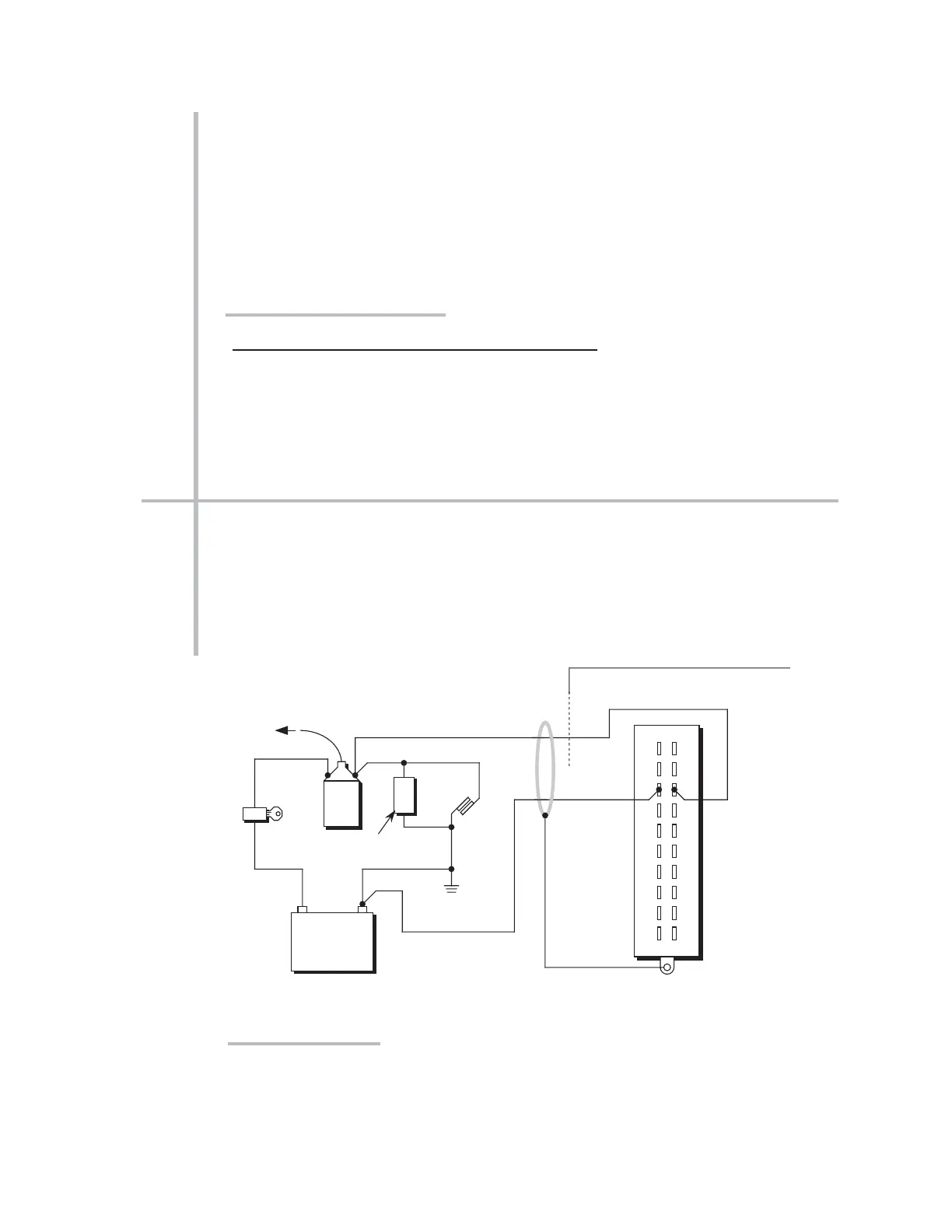
The Model 10A43’s I/O CONNECTOR mates with Daytronic CONDITIONER CONNEC-
TOR No. 60322, shown in Fig. 1.5 (in Manual Section 1.E.1). Fig. 1 shows how the +SIG-
NAL and –SIGNAL pins are to be wired to the engine. Connect the +SIGNAL line (from
Pin 3) directly to the “most negative” terminal of the engine's coil (i.e., the terminal
which is connected to the condenser, not to the battery). Connect the –SIGNAL line
(from
Pin C) either to the negative terminal of the vehicle battery or directly to the
vehicle chassis (GROUND).
10A43.2 TRANSDUCER CONNECTIONS
10A43 DWELL ANGLE CARD
CONDITIONER CONNECTOR (No. 60322)



 To Next Page