2 TRANSDUCER CONNECTIONS
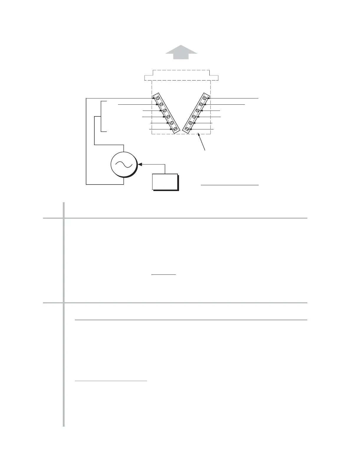
The Model 10A68-2 mates with a special CONDITIONER CONNECTOR BOARD, shown
in Fig. 1. This board has a separate screw-terminal block for each of the 10A68-2’s
two channels. As shown in the figure, the screw terminal to which you connect an AC
signal source will depend on the
input range that has been set for that channel and
whether the input represents
voltage or current.
NOTE: TO MINIMIZE THE EFFECTS OF STRAY CAPACITIVE PICKUP, IT IS STRONGLY
RECOMMENDED THAT ALL UNUSED
INPUT TERMINALS BE TIED TO THEIR RESPEC-
TIVE “COMMON” TERMINAL.
3 SETUP AND/OR OPERATING CONSIDERATIONS
3.a CONFIGURATION AND CALIBRATION
For initial configuration of ANALOG INPUT CHANNELS dedicated to a specific Model
10A68-2 card when used in System 10, see the general remarks on System 10 “real-
channel” configuration in Manual Section 1.G.1 and elsewhere in the
System 10 Guide-
book
. For 10A68-2 channel “type” codes, see Table 2, above.
In System 10, you can use two calibration methods with the Model 10A68-2:
ABSOLUTE CALIBRATION
Described in Manual Section 1.G.3.b, this method is applicable only when the 10A68-2
is being used to measure
voltage or amperage itself. In this case, the user need only
specify an appropriate SCALING FACTOR (“m” coefficient), once the 10A68-2-based
input channel has been properly configured.
TRANSDUCER CONNECTIONS SETUP AND/OR OPERATING CONSIDERATIONS 10A68-2.3
 Loading...