4 OPTIONAL BRIDGE COMPLETION:
MODEL 10CJB-2 DUAL BRIDGE COMPLETION CARD
4.a PURPOSE
The optional Model 10CJB-2 Dual Bridge Completion Card lets you connect each
of your Model 10A72-2C’s inputs to a
2-wire 1/4-bridge, 3-wire 1/4-bridge, 1/2-bridge,
or full-bridge strain gage configuration. Each 1/4-bridge configuration may use either
120 or 350 ohms
nominal gage resistance. The function of the Model 10CJB-2 is to
“complete” the connected bridge—that is, to allow it to be “seen” by the Model 10A72-
2C as a full (4-arm) Wheatstone bridge.
For calibration of 10A72-2C channels originating from the Model 10CJB-2, see Section
4.c, below.
4.b 10CJB-2 TRANSDUCER CONNECTIONS
Remove the top plate of the Model 10CJB-2 box (4 screws in corners). Inside the box
are two sets of labelled screw terminals, one for each of the 10A72-2C’s input chan-
nels (“A” and “B”). You will connect your gage wires directly to these terminals, as
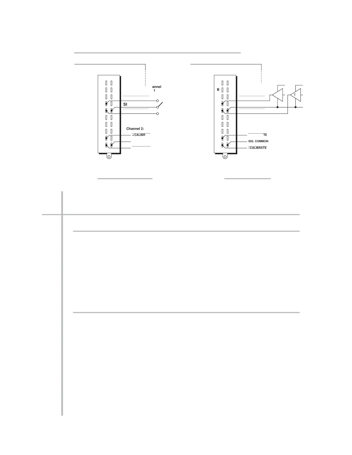
shown in Fig. 6, and, if necessary, interconnect certain terminal pairs by means of
jumper wires. Gage leads should enter the 10CJB-2 through the cutout on the right-
hand side of the box.
NOTE: You must furnish your own
pin-to-pin shielded cable for connecting the
10CJB-2 to the 10A72-2C’s rear I/O CONNECTOR (see Table 2 for pin assignments)—
or you may use a special cable furnished by Daytronic. In either case, Daytronic will
supply terminal connectors for the cable.
ENHANCED DUAL DC STRAIN GAGE CARD 10A72-2C
OPTIONAL BRIDGE COMPLETION 10A72-2C.9
CONDITIONER CONNECTOR (No. 60322)
SIG. COMMON
SIG. COMMON
CONDITIONER CONNECTOR (No. 60322)
SIG. COMMON
SIG. COMMON



 To Next Page