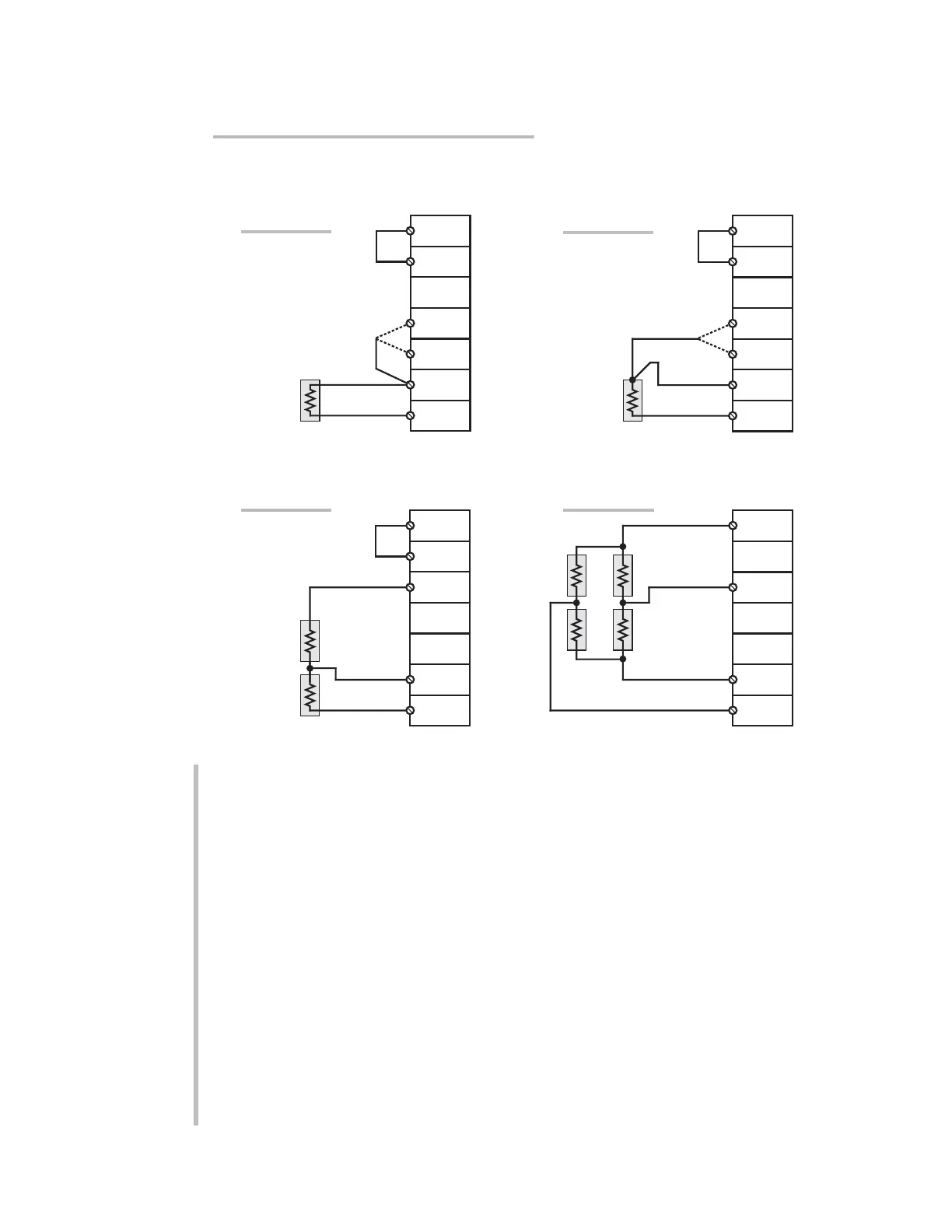
Fig. 6(a) shows connections between the 10CJB-2 and a 2-wire 1/4-bridge gage con-
figuration (represented by the single gage resistor). Here, you must install a jumper
wire between the
–SIG and 1/2 BR terminals, and between the +SIG terminal and
either the 120 terminal or the 350 terminal, depending on the nominal gage resis-
tance.
Fig. 6(b) shows connections between the 10CJB-2 and a 3-wire 1/4-bridge gage con-
figuration (again represented by the single gage resistor). Here again, the
–SIG and
1/2 BR terminals must be tied. The gage’s third (self-compensating) lead is connect-
ed
either to the 120 terminal or to the 350 terminal, depending on the nominal gage
resistance.
Fig. 6(c) shows connections between the 10CJB-2 and a 1/2-bridge gage configura-
tion (represented by the two connected gage resistors). Here again, the
–SIG and
1/2 BR terminals must be tied.
Fig. 6(d) shows connections between the 10CJB-2 and a
full-bridge gage configura-
tion (represented by the four connected gage resistors).
10A72-2C.10 OPTIONAL BRIDGE COMPLETION
10A72-2C ENHANCED DUAL DC STRAIN GAGE CARD
(Chn. 1 or 2)
(Chn. 1 or 2)
(Chn. 1 or 2)
(Chn. 1 or 2)



 To Next Page