To create your first “real-world” DATA CHANNEL, you should now connect at least
one transducer to your mainframe. This should be a transducer that can be both
zeroed and loaded with an arbitrary value of the measured parameter (NOT, in
most cases, a Thermocouple, Thermistor, or RTD). A perfect example of such a
transducer is a
load cell.
You will use this channel for the procedures given in the following sections. For a
listing of all
preconfigured data channels in your particular system, see the print-
out in
Appendix A of your System 10 Guidebook.*
NOTE: While most CONDITIONER CARDS are ready to be calibrated as soon as
they are properly cabled to their respective transducers, a few of them require
special setup procedures under certain circumstances. Be sure to check the
section entitled “SETUP AND/OR OPERATING CONSIDERATIONS” in each card-
specific subsection of
System 10 Guidebook Section 1.E.2 that applies to your
system.
7
DATA CHANNEL CONFIGURATION
In this section, we will consider the configuration of your system’s REAL CHAN-
NELS. A “real channel” is an analog input channel containing physical measure-
ment data from the “real world.” There are other types of data channels that must
be configured before they can be used—including ANALOG OUTPUT CHANNELS,
PSEUDOCHANNELS, and CONVERSION CHANNELS. You need not worry about
these other types of channels right now.
NOTE: IN ALMOST ALL CASES, YOUR SYSTEM’S ANALOG-INPUT CHANNELS
WILL HAVE BEEN FULLY CONFIGURED AT THE FACTORY, IN ACCORDANCE
WITH SPECIFICATIONS GIVEN AT THE TIME OF ORDER. Therefore, you need not
normally concern yourself (at least initially) with the configuration procedure,
unless you need to
reconfigure your system, through the addition or removal of
one or more cards, the reassignment of transducer inputs, the physical inter-
change of cards within the mainframe, etc.
“Configuration” of a real channel ordinarily involves applying to that channel first a
TYPE (TYP) command and then a LOCATE (LCT) command. In the following
B - 16
DATA CHANNEL CONFIGURATION
“O
NTHE
A
IR
” (B-S
IZED
)
* Only present for strain gage
conditioner cards.
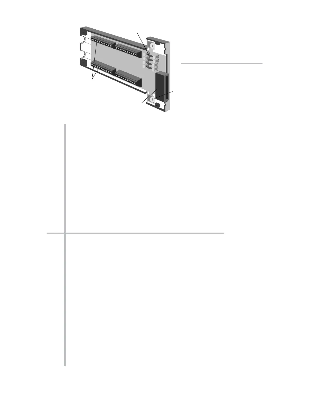
Fig. 6.1.b Typical “AA”
Conditioner Connector
Assembly (shown upside down)
* PLEASE NOTE: The System 10 Data Sheet will be included within the System 10 Guidebook
itself (as Appendix A) only when a printed version of the Guidebook is supplied with a specific
System 10. WHEN THE GUIDEBOOK IS PROVIDED ON CD OR OTHER ELECTRONIC MEDIUM,
THE DATA SHEET WILL BE PROVIDED AS A SEPARATE DOCUMENT.
 Loading...