2 TRANSDUCER CONNECTIONS
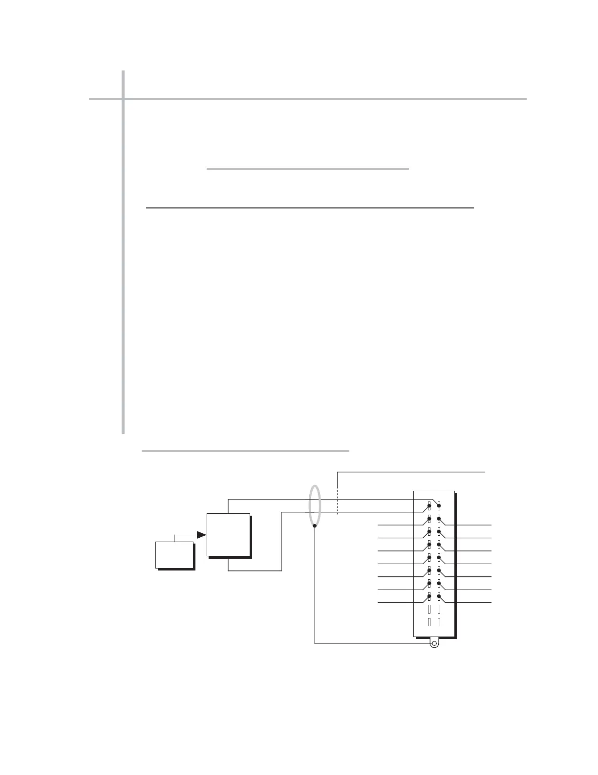
The Model 10A62-8C’s I/O CONNECTOR mates with Daytronic CONDITIONER CON-
NECTOR No. 60322, shown in Fig. 1.5 (in Manual Section 1.E.1). Standard cabling is
shown in Fig. 1. Table 2 gives standard pin assignments for the I/O Connector.
Table 2 Model 10A62-8C Pin Assignments
I/O Connector Conditioner Conditioner
Pin Channel Line
Number Number Function
11+SIGNAL
A1–SIGNAL
22+SIGNAL
B2–SIGNAL
33+SIGNAL
C3–SIGNAL
44+SIGNAL
D4–SIGNAL
55+SIGNAL
E5–SIGNAL
66+SIGNAL
F6–SIGNAL
77+SIGNAL
H7–SIGNAL
88+SIGNAL
J8–SIGNAL
9,K,10,L Not Committed
10A62-8C.2 TRANSDUCER CONNECTIONS
10A62-8C EIGHT-CHANNEL 4-20 MA CARD
CONDITIONER CONNECTOR (No. 60322)
Reg. Power



 To Next Page