1-23
TRANSDUCER CABLING
AND
CONDITIONER CARD SETUP
1.E
1.E.1 GENERAL CONSIDERATIONS
* Note that the Model 10A68-2 Dual AC RMS Conditioner Card mates with a special condi-
tioner connector board that has a separate screw-terminal block for each of the two inputs,
while the Model 10A73-4 Quad 1/2 & 1/4 Bridge Strain Gage Conditioner Card usually
mates with a special 1/4-bridge, 1/2-bridge, or full-bridge COMPLETION CONNECTOR (see
the respective cabling diagrams in Section 1.E.2).
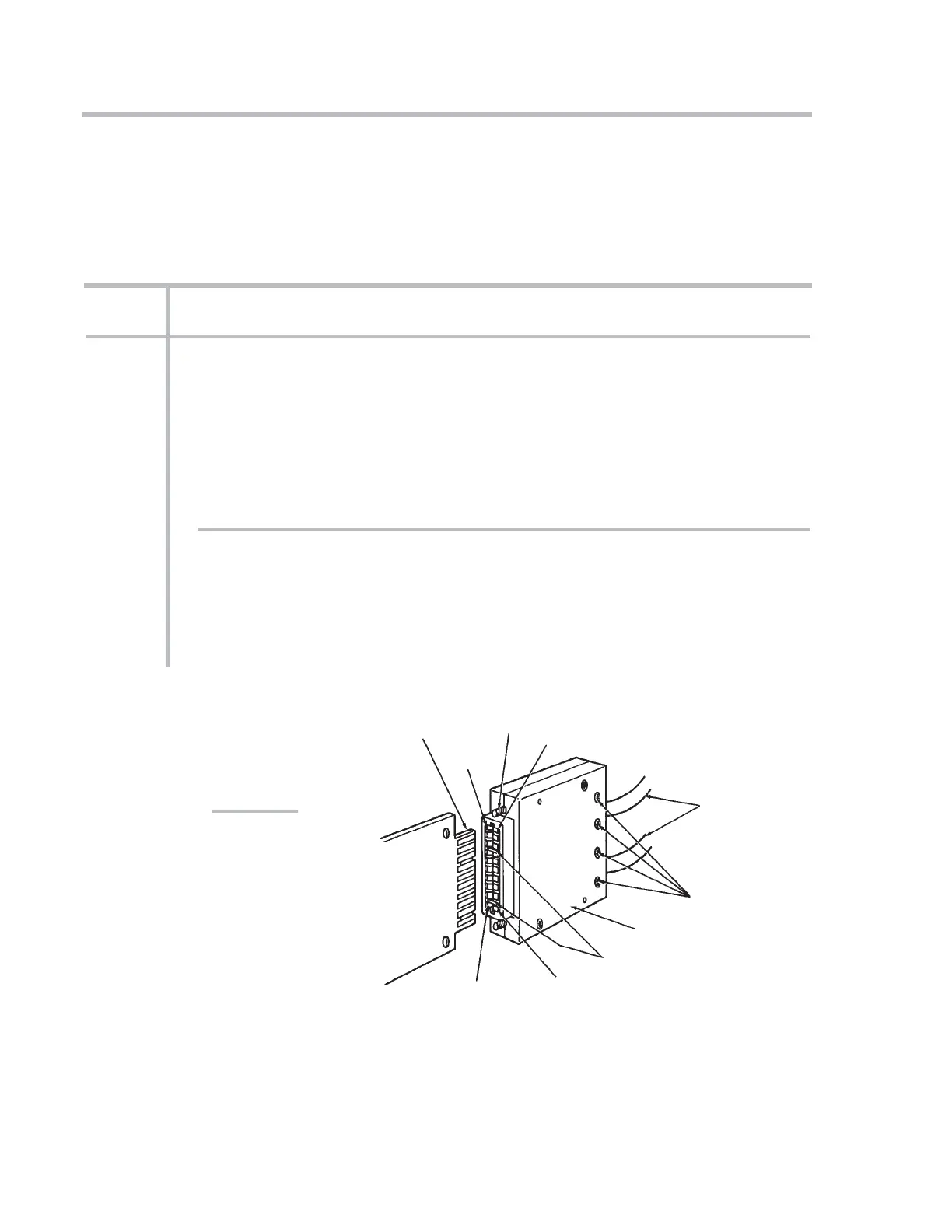
"10A"-Card
I/O Connector
(rear of mainframe)
"10A"
Conditioner
Card
20-Pin Conditioner
Connector
(No. 60322)
Pin 1
Pin A
Pin 10
Pin L
Cables to
Transducers
Cable Clamp-Bar
Screws
Captive Screw
(for mounting to
mainframe)
Connector
"Keys"
(to match slots in
card I/O Connector)
Fig. 1.5 Standard “10A”
Conditioner Connector
(No. 60322)
SYSTEM 10 GUIDEBOOK
1.E TRANSDUCER CABLING AND
CONDITIONER CARD SETUP
1.E.1 GENERAL CONSIDERATIONS
If you ordered one or more sensor cables with your System 10, each supplied
cable will be equipped with an individual female CONDITIONER CONNECTOR.
The type of connector will depend on the conditioner card with which it is to mate.
There are two basic types of Daytronic conditioner cards (for complete descrip-
tions and specifications, see the latest Daytronic
Conditioner Cards Catalog or
Section 1.E.2, below):
a. “10A” CARDS
Many of these cards—originally designed for Daytronic’s System 10—may now be
used in the
SPS6000 and SPS8000 Systems as well. Sensor cables for most
10A cards use the female 20-pin CONDITIONER CONNECTOR (Daytronic Part No.
60322), shown in Fig. 1.5.* This connector allows direct
solder-terminal attach-
ment of up to eight separate transducer cables. The connector’s internal solder
terminals are labelled 1 through 10 and A through L. These designations corre-



 To Next Page