10A10-4 require special screw-terminal connectors, similar to that shown in Sec-
tion 1.E of the
System 10 Guidebook.*
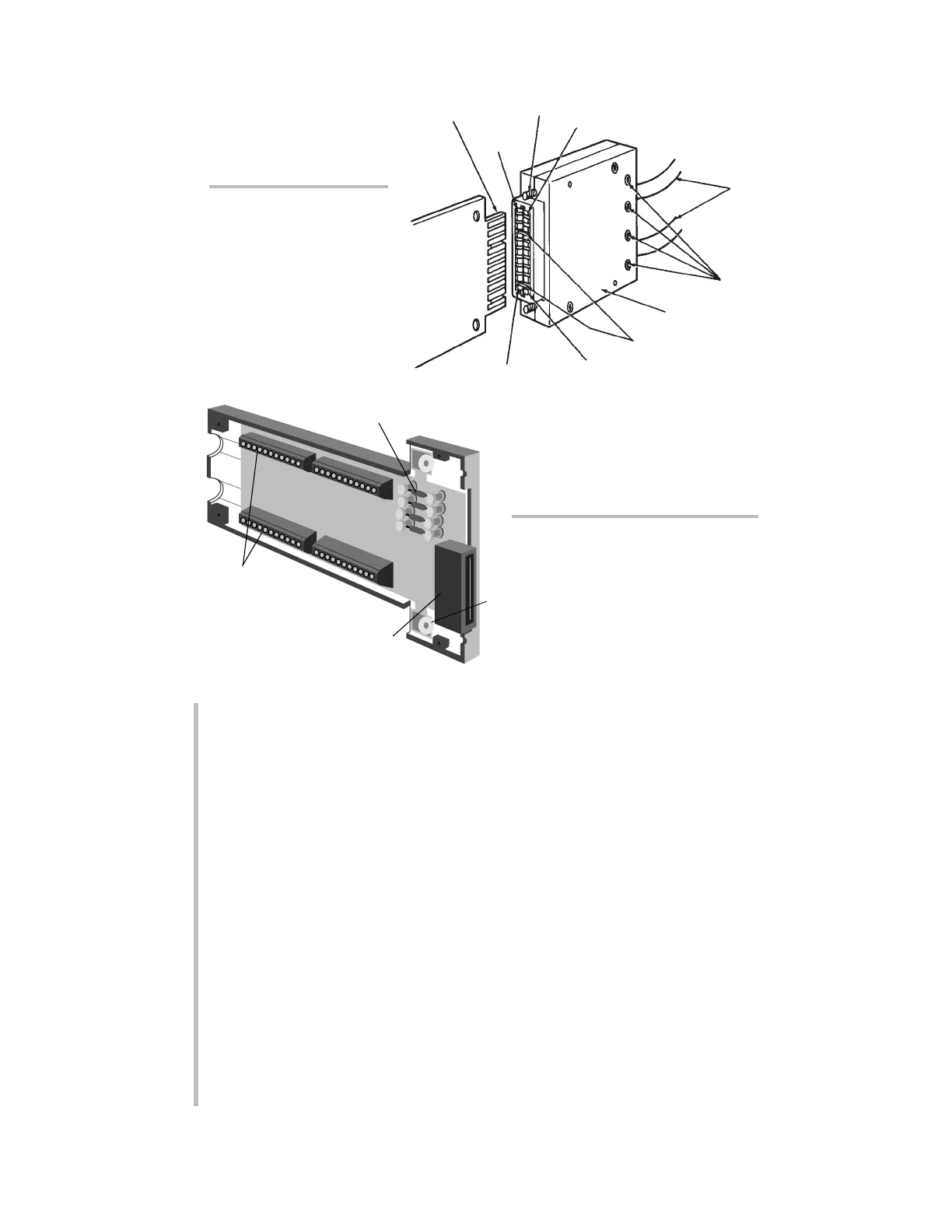
Fig. 6.a.b shows a typical 40-pin connector for a Daytronic
“AA” Conditioner Card,
with labelled
screw terminals for direct connection of transducer cable leads.
If you’re supplying your own sensor cables, you should carefully read Section 1.E
of the
System 10 Guidebook, along with the individual conditioner card subsec-
tion(s) of Section 1.E.2
that apply to your system. All necessary cabling instruc-
tions are given here.
To create your first “real-world” DATA CHANNEL, you should now connect at least
one transducer to your mainframe. This should be a transducer that can be both
zeroed and loaded with an arbitrary value of the measured parameter (NOT, in
most cases, a Thermocouple, Thermistor, or RTD). A perfect example of such a
transducer is a
load cell.
A - 10
“O
NTHE
A
IR
” (A-S
IZED
)
"10A"-Card
I/O Connector
(rear of mainframe)
"10A"
Conditioner
Card
20-Pin Conditioner
Connector
(No. 60322)
Pin 1
Pin A
Pin 10
Pin L
Cables to
Transducers
Cable Clamp-Bar
Screws
Captive Screw
(for mounting to
mainframe)
Connector
"Keys"
(to match slots in
card I/O Connector)
Fig. 6.1.a Standard “10A”
Conditioner Connector
Fig. 6.1.b Typical “AA”
Conditioner Connector
Assembly (shown upside down)
* Only present for strain gage
conditioner cards.
*Several other “10A” cards require special I/O provisions. For example, the Model 10A68-2
Dual AC RMS Conditioner Card mates with a special connector board that has a separate
screw-terminal block for each input channel, and the Model 10A74-4C Quad Strain Gage
Track-Hold Conditioner Card will normally use a special Bridge Completion Connector in place
of the standard connector. See the specific subsection of System 10 Guidebook Section 1.E.2
for complete details.
SETUP OF ANALOG INPUTS: TRANSDUCER CABLING
 Loading...