DSE Model 5310 Automatic Mains Failure & Instrumentation System Operators Manual
38 Part No. 057-013 5310 OPERATING MANUAL ISSUE 7.1 18/06/2007 ADM
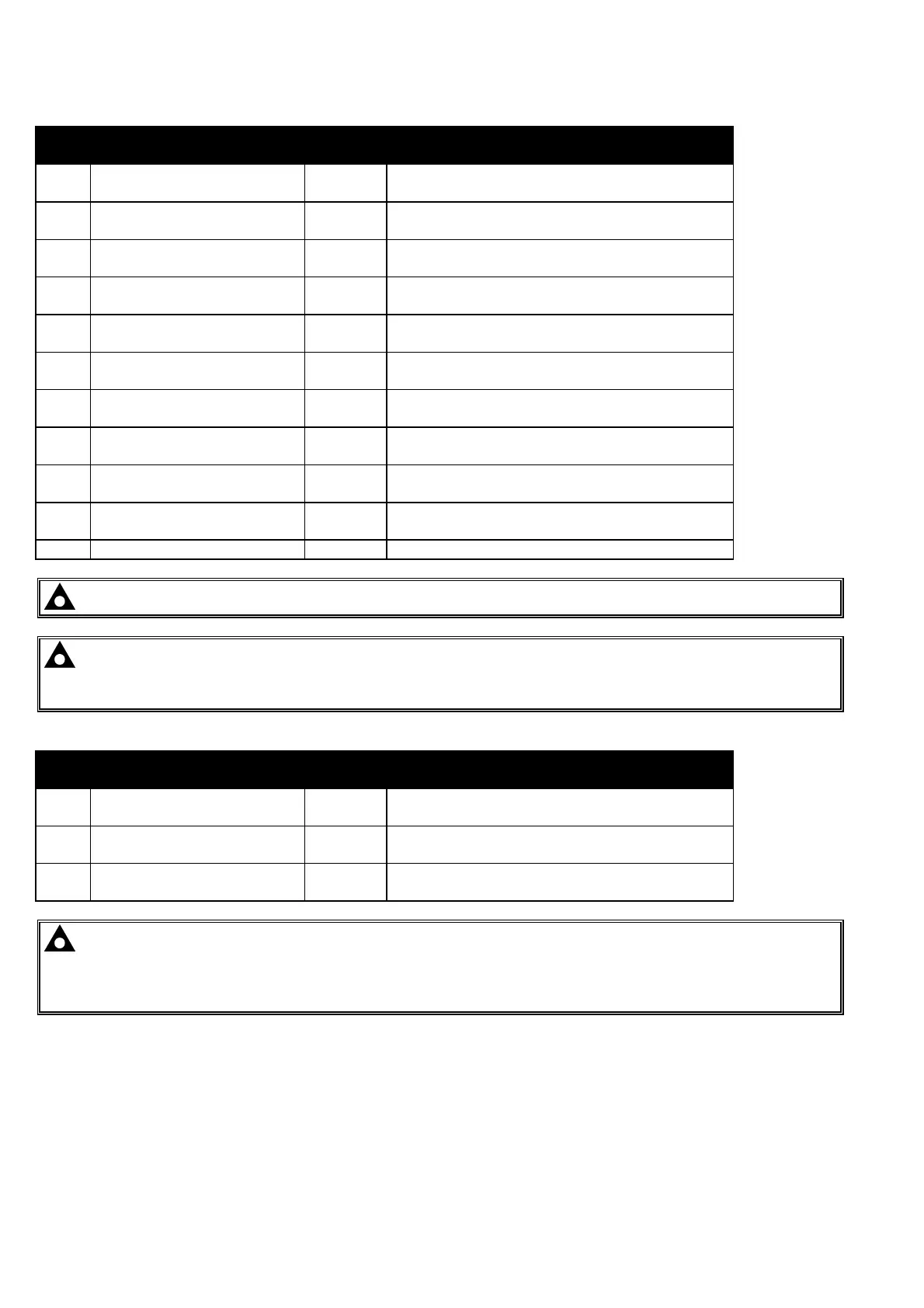
8.1.2 PLUG “B” 11 WAY
PIN
No
DESCRIPTION CABLE
SIZE
NOTES
9 Charge fail / excite 2.5mm²
AWG 13
Do not connect to ground (battery Negative)
10 Auxiliary input 1 0.5mm²
AWG 20
Switch to Negative
11 Auxiliary input 2 0.5mm²
AWG 20
Switch to Negative
12 Auxiliary input 3 0.5mm²
AWG 20
Switch to Negative
13 Auxiliary input 4 0.5mm²
AWG 20
Switch to Negative
14 Auxiliary input 5 0.5mm²
AWG 20
Switch to Negative
15 Auxiliary input 6 0.5mm²
AWG 20
Switch to Negative
16 Functional Earth 2.5mm²
AWG 13
Connect to a good clean earth point
17 Magnetic pickup Positive 0.5mm²
AWG 20
Connect to Magnetic Pickup device
18 Magnetic pickup Negative 0.5mm²
AWG 20
Connect to Magnetic Pickup device
19 Not connected -
NOTE:- Ensure magnetic pickup screen is connected to ground at one end only.
NOTE:- When the module is configured for CAN operation, terminals 17 & 18 should be left
unconnected. Engine speed is transmitted to the 53xx controller on the CAN link.
Refer to CAN and DSE Wiring for further information.
8.1.3 PLUG “C” 3 WAY
PIN
No
DESCRIPTION CABLE
SIZE
NOTES
20 CAN port Common 0.5mm²
AWG 20
Use only 120Ω CAN approved cable
21 CAN port H 0.5mm²
AWG 20
Use only 120Ω CAN approved cable
22 CAN port L 0.5mm²
AWG 20
Use only 120Ω CAN approved cable
NOTE:- Screened 120Ω impedance cable specified for use with CANBUS must be used.
DSE stock and supply Belden cable 9841 which is a high quality 120Ω impedance cable suitable for
CANbus use (DSE part number 016-030)
Refer to CAN and DSE Wiring for further information.