DSE Model 5310 Automatic Mains Failure & Instrumentation System Operators Manual
62 Part No. 057-013 5310 OPERATING MANUAL ISSUE 7.1 18/06/2007 ADM
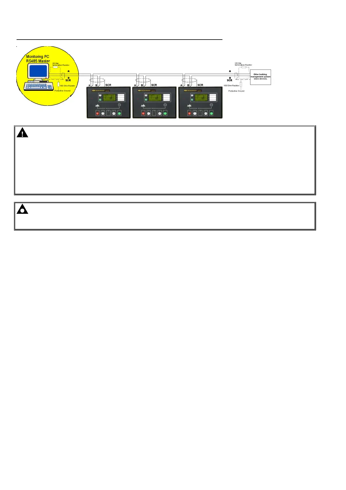
TYPICAL BUILDING MANAGEMENT SCHEME USING RS485 MONITORING
CAUTION! -. RS485 cabling must be 120Ω impedance cable, specified for use with RS485. 120Ω
terminating resistors must be fitted to the first and last devices on the bus. Some PC RS485 cards are
already fitted with this resistor, and in this case should not be fitted externally. If in doubt, consult the
supplier of your PC RS485 card.
If the 5310 controller is the ‘last’ device on the bus, then it’s RS485 connection must be suitably
terminated with a 120Ω resistor as detailed in the specification laid out in the RS485 standard.
Recommended cable BELDEN 9841 120Ω RS485 cable.
DSE part number 016-030.
NOTE: - The RS485 output uses ‘MODBUS’ protocol. It is possible to use third party software to
monitor and control the 5310 module via this protocol.
Please refer to Deep Sea Electronics Plc for details.
14.8.5 MODBUS™
The RS485 output uses Modbus™ communications protocol. This uses a master-slave technique to communicate.
Only the Master can initiate a packet transaction, called a ‘query’. When appropriate the slave (5310 Module)
responds to the query and provides the information requested by the master.
All supported data can be read and written as specified in the register table (documentation is available from Deep
Sea Electronics Plc.).
When the 5310 Module receives a query it will respond by either supplying the requested register data or
performing the requested action. A slave device (the 5310 module) will never initiate communications on the
Modbus™ link. The 5310 can only be configured as a slave device. The Master can only query individual slaves.
Refer to the Modbus™ protocol document for more details.
 Loading...

