PSU LEDs
• Solid green—Input is OK.
• Flashing yellow—There is a fault with the PSU.
• Flashing green blink at 1Hz—Switch is in a standby/CR state.
• O—PSU is o.
AC or DC power supply installation
NOTE: The PSU slides into the slot smoothly. Do not force a PSU into a slot as this action may damage the PSU or the switch.
NOTE: Ensure that you correctly install the PSU. When you install the PSU correctly, the power connector is on the left side of
the PSU.
NOTE: If you use a single PSU, install a blank plate in the other PSU slot. If you are only using one power supply, install the power
supply in the rst slot, PSU1. Install a blank plate in the second slot, PSU2.
1 Remove the PSU slot cover from the S5200F-ON Series switch using a small #1 Phillips screwdriver.
2 Remove the PSU from the electro-static bag.
3 Insert the PSU into the switch PSU slot—insert the exposed PSU connector rst.
The PSU slot is keyed so that you can only fully insert the PSU in one orientation. When you install the PSU correctly, it snaps into
place and is ushed with the back of the switch.
4 Plug in the appropriate AC 3-prongs cable from the switch PSU to the external power source.
5 Repeat steps 1 through 4 if you have a redundant PSU using the second PSU slot on the S5200F-ON Series switch.
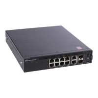
S5224F-ON, S5232F-ON, or S5248F-ON switch PSU:
• 1--PSU1 is on the right side of the switch. PSU2 is on the left side of the switch.
S5296F-ON switch PSU:
50
Power supplies
 Loading...