About this task
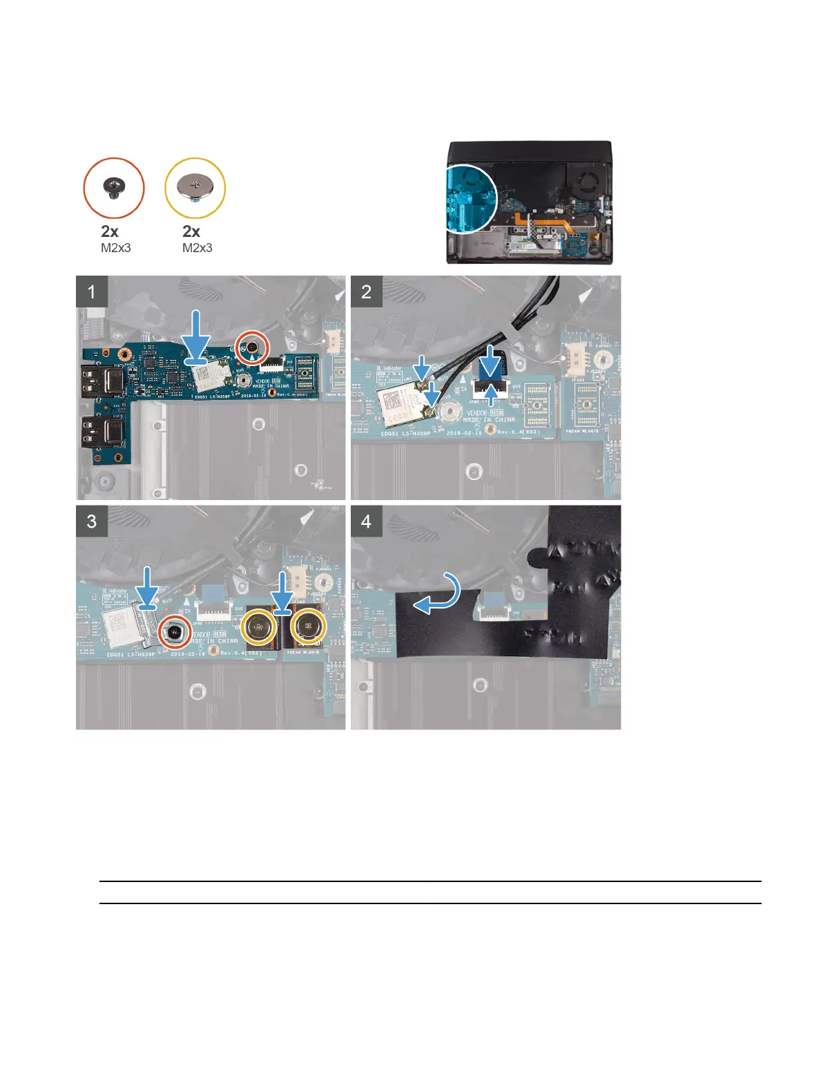
The following image indicates the location of the left I/O-board and provides a visual representation of the installation
procedure.
Steps
1 Using the alignment post, place the left I/O-board on the palm-rest assembly.
2 Replace the screw (M2x3) that secures the left I/O-board to the palm-rest assembly.
3 Connect the power-button assembly-cable to the left I/O-board and close the latch.
4 Connect the antenna cables to the wireless card.
The following table provides the antenna-cable color scheme for the wireless card supported by your computer.
Table 3. Antenna-cable color scheme
Connectors on the wireless card Antenna-cable color
Main (white triangle) White
Auxiliary (black triangle) Black
33