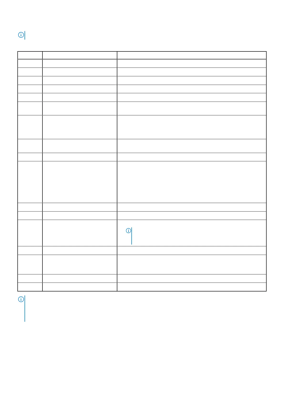
NOTE: Items numbers 4, 5, 7, 11, 12 and 15 are not in use on EX3000.
Table 50. Server indicators, buttons, or connectors
Item Indicator, Button, or Connector Description
1 Blade EN connector (optional) This function is reserved.
2 Serial connector Enables you to connect a serial device to the system.
3 Video connector Enables you to connect a VGA display to the system.
4 Ethernet connector 1 Integrated 10/100/1000 Mbps NIC connector.
5 Ethernet connector 2 Integrated 10/100/1000 Mbps NIC connector.
6 USB connector Enables you to connect USB devices to the system. The port is USB 2.0-
compliant.
7 SD vFlash card slot Provides persistent on-demand local storage and a custom deployment
environment that allows automation of server configuration, scripts and
imaging. For more information, see the Integrated Dell Remote Access
Controller 9 (iDRAC9) User’s Guide.
8 USB connector Enables you to connect USB devices to the system. The port is USB 3.0-
compliant.
9 Dedicated Ethernet port Dedicated management port on the iDRAC ports card.
10 System identification button
● The identification button can be used to locate a particular system
within a rack.
● Press to toggle the system ID on and off.
● If the system stops responding during POST, press and hold the system
ID button for more than five seconds to enter BIOS progress mode.
● To reset iDRAC (if not disabled in F2 iDRAC setup) press and hold the
button for more than 15 seconds.
11 Ethernet connector 3 Integrated 10/100/1000 Mbps NIC connector.
12 Ethernet connector 4 Integrated 10/100/1000 Mbps NIC connector.
13 Power button
● The power button controls the PSU output to the system.
●
NOTE: On ACPI-compliant operating systems (OSs), turning off
the system using the power button causes the system to perform a
graceful shutdown before power to the system is turned off.
14 Boot SSD 2.5-inch boot SSD
15 SSD in rear slots Optional 960GB SATA MU SSD read cache.
● This feature is optional and available only with 3.5 and above. For more
information, see ECS Appliance SSD Read Cache Deployment guide.
16 Power supply units Two redundant power supply units (PSUs) for sled A.
17 Power supply units Two redundant power supply units (PSUs) for sled B.
NOTE:
● Features of sled B are for EX3000D dual-node systems only.
● A dummy sled (sled B) will be installed over the sled A compartment and two dummy PSUs over the PSU slots for sled B
in the EX3000S single-node system.
EX3000 disk drives
Describes the disk drives that are integrated into the server chassis of the EX3000 appliance.
The EX3000 4U chassis contains one or two server sleds, depending on whether the chassis is a single or dual node
configuration. Both chassis configurations support the 12 TB 3.5" 6 Gb/s SATA 512e and 16 TB SATA 512e disk drives.
EX3000 Platform
133
 Loading...