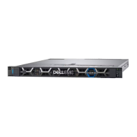
The numbered front-end switch ports used for connecting to the ports on the EXF900 nodes are shown in the following
diagram. Port 1 on the Hare switch (FE2) connects to port 4 on Node 1. Port 2 on the Hare switch (FE2) connects to port 4 on
Node 2, and so on. Similarly, Port 1 on the Rabbit switch (FE1) connects to port 3 on Node 1. Port 2 on the Rabbit switch (FE1)
connects to port 3 on Node 2, and so on.
Figure 36. Node ports on front-end switches
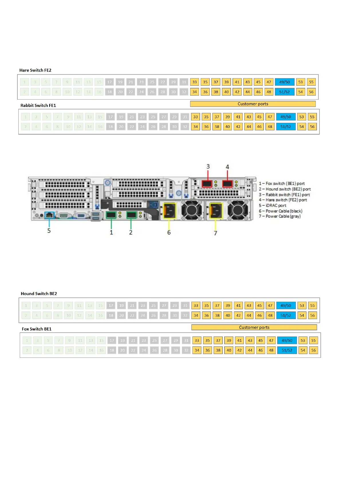
Figure 37. Back-end switch, front-end switch, and iDRAC ports on an EXF900 node
The numbered back-end switch ports used for connecting to the ports on the EXF900 nodes are shown in the following
diagram. Port 1 on the Hound switch (BE2) connects to port 2 on Node 1. Port 2 on the Hound switch (BE2) connects to port
2 on Node 2, and so on. Similarly, Port 1 on the Fox switch (BE1) connects to port 1 on Node 1. Port 2 on the Fox switch (BE1)
connects to port 1 on Node 2, and so on.
Figure 38. Node ports on back-end switches
EXF900 Platform
55
 Loading...