EX500 iDRAC cabling
Review the wiring diagrams for the iDRAC cables that connect the iDRAC port on the node to the Fox back-end switch.
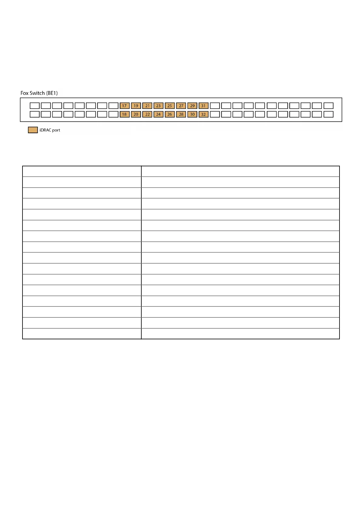
The Fox switch (BE1) port numbers used for connecting to the iDRAC ports on the EX500 nodes are shown in the following
diagram.
Figure 55. Fox switch iDRAC ports
Table 36. EX500 node iDRAC port to BE1 port mapping
Node 1 iDRAC port BE1 Port 17
Node 2 iDRAC port BE1 Port 18
Node 3 iDRAC port BE1 Port 19
Node 4 iDRAC port BE1 Port 20
Node 5 iDRAC port BE1 Port 21
Node 6 iDRAC port BE1 Port 22
Node 7 iDRAC port BE1 Port 23
Node 8 iDRAC port BE1 Port 24
Node 9 iDRAC port BE1 Port 25
Node 10 iDRAC port BE1 Port 26
Node 11 iDRAC port BE1 Port 27
Node 12 iDRAC port BE1 Port 28
Node 13 iDRAC port BE1 Port 29
Node 14 iDRAC port BE1 Port 30
Node 15 iDRAC port BE1 Port 31
Node 16 iDRAC port BE1 Port 32
EX500 Platform 81
 Loading...