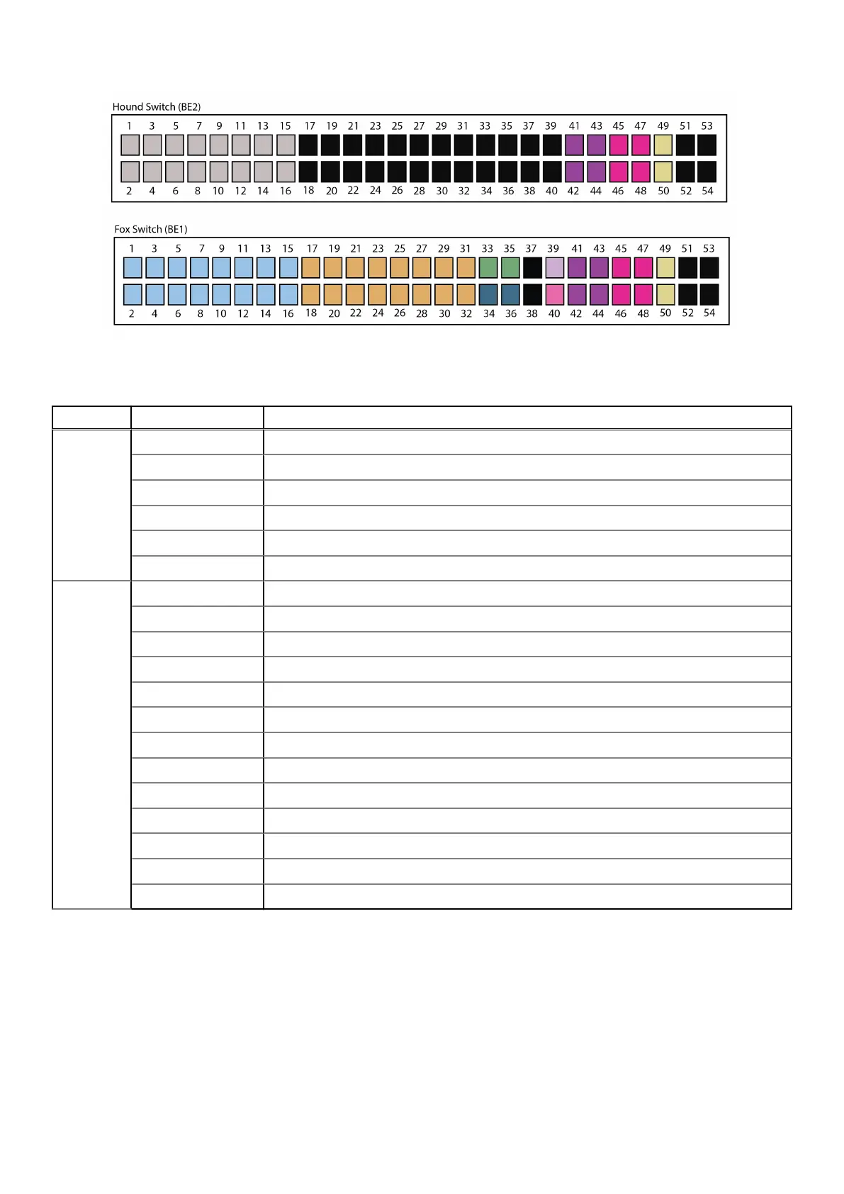
Figure 3. Back-end switches
Table 4. Switch port number
Switch Port number Description
Hound 1-16 Private network ports connected to nodes (10/25 GbE)
17-40 Not designated.
41-44 In from EX-Series rack when the ECS system has more than one rack (10/25 GbE)
45-48 Out to EX-Series rack when the ECS system has more than one rack (10/25 GbE)
49-50 VLT ports (100 GbE)
51-54 Not designated (100 GbE)
Fox 1-16 Private network ports connected to nodes (10/25 GbE)
17-32 iDRAC ports
33 To Rabbit (FE1) switch
34 To service tray in front
35 To Hare (FE2) switch
36 Open for rear service connectivity
37-38 Not designated
39 In from Gen2 Turtle switch
40 Out to Gen2 Turtle switch
41-44 In from EX-Series rack when the ECS system has more than one rack (10/25 GbE)
45-48 Out to EX-Series rack when the ECS system has more than one rack (10/25 GbE)
49-50 VLT ports (100 GbE)
51-54 Not designated (100 GbE)
Front-end and back-end switch connections
The front-end switch management ports connect to back-end switch ports via two CAT6 cable and two 1GBaseT SFP.
These two cables and two SFP are used for Dell EMC switches. If you are deploying in a third party rack with customer
switches, or using customer switches in a Dell EMC rack, these two cables and two SFP are not required.
The connection between the front-end switch ports and back-end switch ports are as follows:
● Hare (FE2) to Fox (BE1)
Switches
15
 Loading...