5 Place the display assembly base on a clean and at surface with the display panel facing down.
6 Replace the 8 (M3x5) screws that secure the display panel to the middle frame and display assembly base 1 .
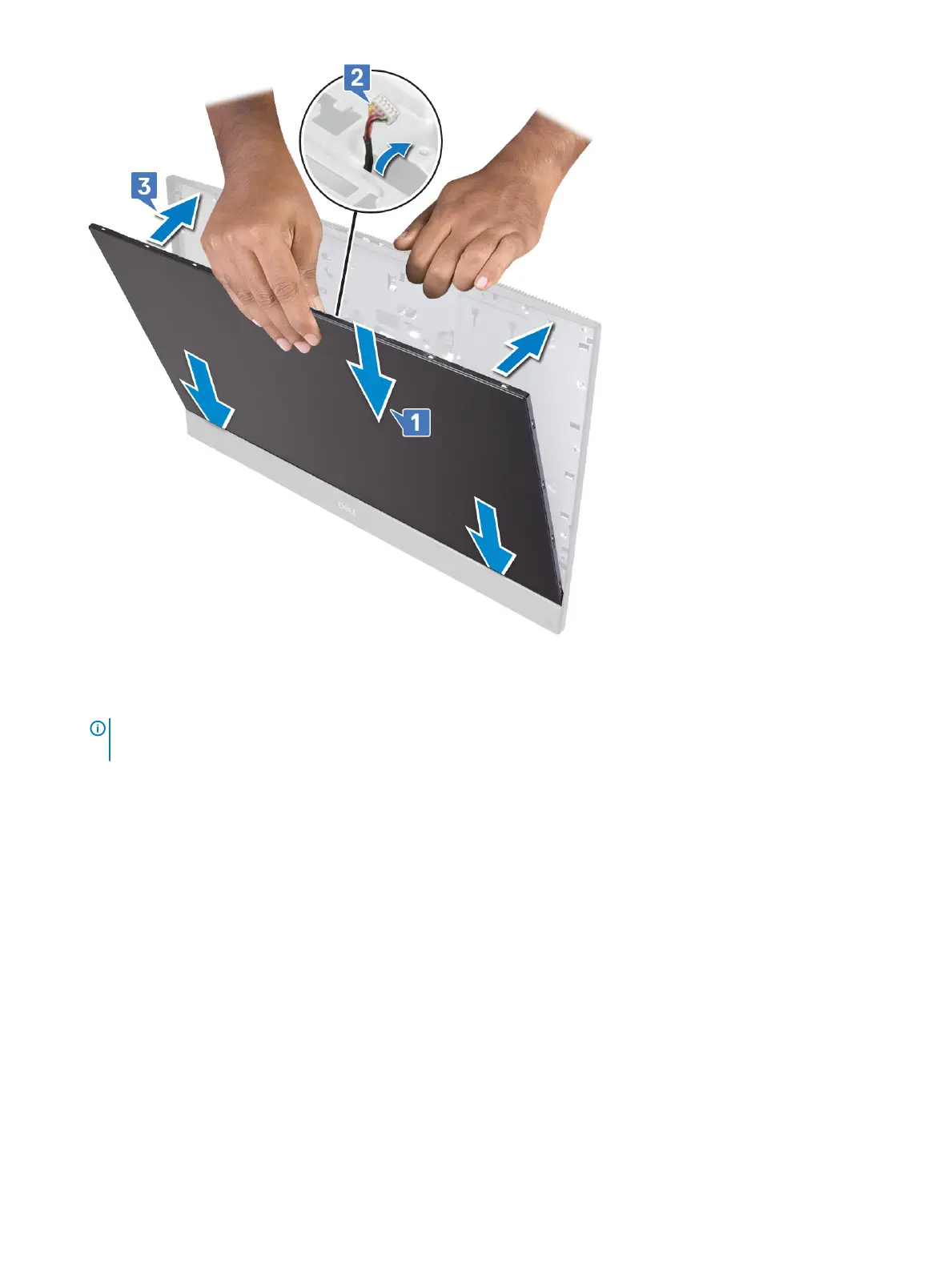
7 Route the display backlit cable through the routing guides on the display assembly base 2.
NOTE
: The screws that secure the middle frame and display assembly base to the display panel are silver in color and
etched with "LCD" around the screw holes.
100 Removing and Installing components