j Heat sink
k Processor
l Base cover
m I/O bracket.
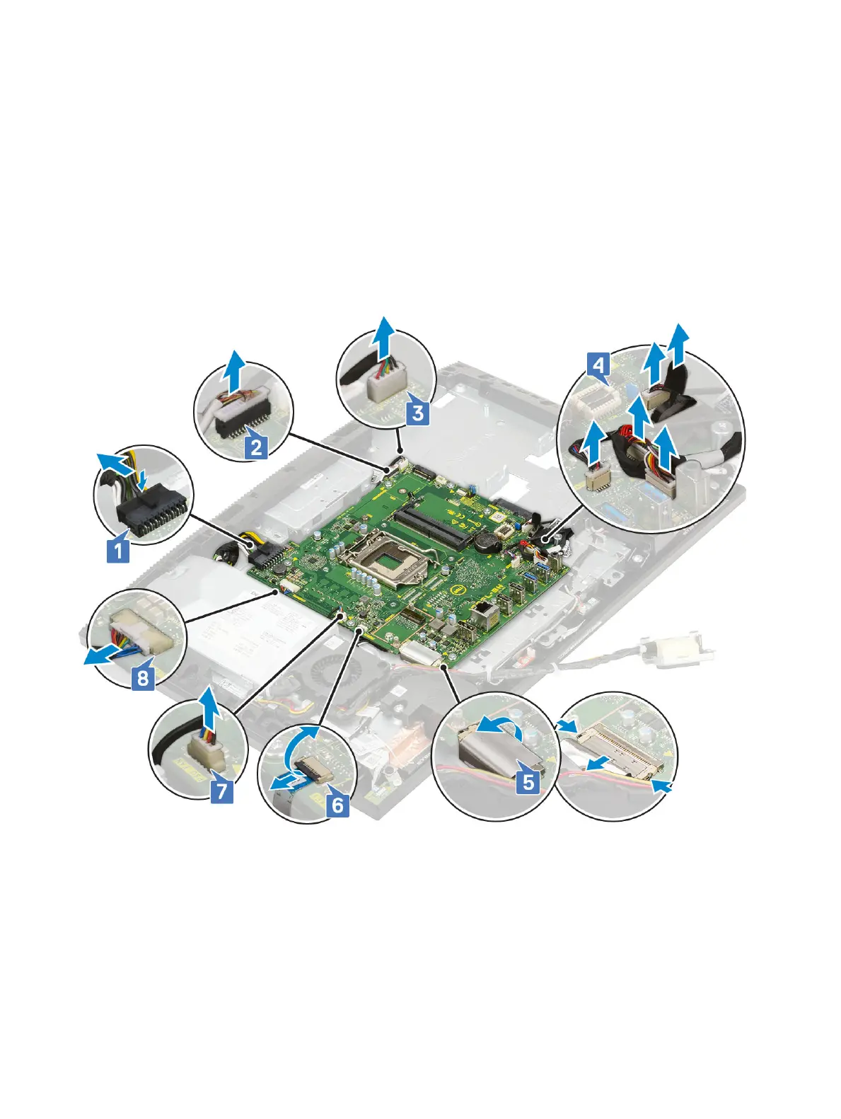
3 Disconnect the following cables from the system board:
• Power supply unit cable [1]
• Camera cable [2]
• Touch cable [3]
• SIO_power,SIO_signal, UAJ, INT_speaker,DMIC cables [4]
• LVDC cable [5]
• Power button board cable [6]
• PSU fan cable [7]
• Back light cable [8]
4 Remove the eight screws (M3x5) that secure the system board to the display assembly base [1].
5 Lift the system board o the display assembly base [2].
72
Removing and Installing components