f System fan
g Hard drive
h WLAN card
i System board
j PSU
k PSU fan
l Camera
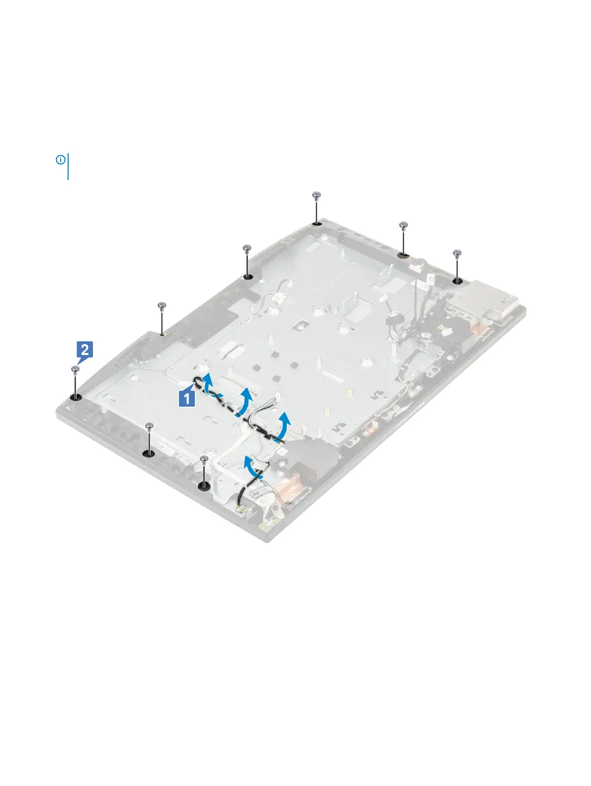
3 Remove the display backlight cable from the routing guides on the display assembly base [1].
4 Remove the 8 screws (M3x5) that secure the middle frame and display assembly base to the display panel [2].
NOTE: The screws that secure the middle frame and display assembly base to the display panel are silver in color and
etched with "LCD" around the screw holes.
5 Place the system in upright position, holding the display panel and display assembly base, carefully release the display panel from
middle frame and display assembly base [1].
6 Slide the display backlit cable through the slot on the display assembly base [2].
7 Lift the display panel o the middle frame and display assembly base [3].
98
Removing and Installing components