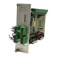
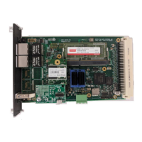
Accessory 24E2A
Board Configuration
An Acc-24E2A comes standard with one Servo IC providing four servo interface channels, which are
brought out on terminal blocks (standard) or DB15 connector. Each channel of servo interface circuitry
includes the following:
•
•
•
•
•
Two output command signal sets, configurable as either:
One pulse-and-direction
Two DAC outputs
3-channel differential/single-ended encoder input
Eight input flags, two output flags
Option 1A: If Option 1A is ordered, the circuitry and input/output connectors are provided for the third
and fourth channels associated with the Servo IC on the main Acc-24E2A. The command signals for this
option are ±10V.
Option 1D: If Option 1D is ordered, the circuitry and input/output connectors are provided for the third
and fourth channels associated with the Servo IC on the main Acc-24E2A. The command signals for this
option are digital PWM signals for direct PWM commutation. The option 1D description can be found in
the Acc-24E2 manual.
Option DB: If the option DB is ordered the outputs and inputs to the amplifiers and encoders will be
serviced from DB15 connectors. See Acc-24E2A DB15 Connector Option section for pin outs.
2 Introduction
 Loading...