Accessory 24E2A
This technique requires that both signal lines of the pair have pull-up resistors. Note that this is not the
default configuration of a PMAC as it is shipped. The complementary lines (A/ and B/) are pulled to
2.5V in a voltage-divider configuration as shipped to be able to accept both single-ended and normal
differential inputs. This must be changed to a pull-up configuration which involves reversing a socketed
resistor pack on the Acc-24E2A.
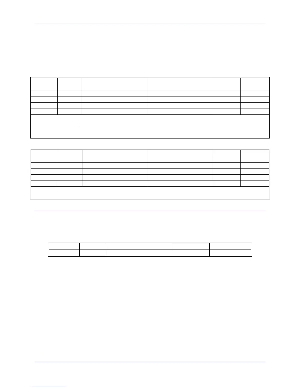
Acc-24E2A Encoder Loss Detection with UMAC Turbo CPU
Channel Resistor
Pack
Status Bit Address (Even-
Numbered Servo IC)*
Status Bit Address (Odd-
Numbered Servo IC)*
Status Bit
Name
Bit Error
State
1 RP22 Y:$07xF08,5 Y:$07xF0C,5 QL_1- 0
2 RP24 Y:$07xF09,5 Y:$07xF0D,5 QL_2- 0
3 RP22** Y:$07xF0A,5 Y:$07xF0E,5 QL_3- 0
4 RP24** Y:$07xF0B,5 Y:$07xF0F,5 QL_4- 0
*The x digit in this hex address matches the value (8, 9, A, or B) in the fourth digit from the right in the board’s own
base address (e.g. $079
200). If alternate addressing of Servo ICs is used (e.g. Servo IC 2*), add $20 to these
addresses.
**These resistor packs are on the Option 1A piggyback board (if present) of the module, not on the baseboard.
Acc-24E2A Encoder Loss Detection with UMAC MACRO CPU
Channel Resistor
Pack
Status Bit Address (First-
Servo IC)*
Status Bit Address
(Second Servo IC)*
Status Bit
“Name”
Bit Error
State
1 RP22 Y:$B8C8,5 Y:$B8EC,5 QL_1- 0
2 RP24 Y:$B8C9,5 Y:$B8ED,5 QL_2- 0
3 RP22** Y:$B8CA,5 Y:$B8EE,5 QL_3- 0
4 RP24** Y:$B8CB,5 Y:$B8EF,5 QL_4- 0
*First Servo IC has base address $C040; second Servo IC has base address $C060
**These resistor packs are on the Option 1A piggyback board (if present) of the module, not on the baseboard.
Position Compare Port Driver IC
As with the other PMAC controllers, the UMAC has the high-speed position compare outputs allowing
the firing of an output based on position. This circuit will fire within 100 nsec of reaching the desired
position. The position compare output port on Acc-24E2x has driver IC at component U27.
The following table lists the properties of each driver IC:
Part # of Pins Max Voltage and Current Output Type Max Frequency
DS75451N 8 5V, 10 mA Totem-Pole 5 MHz
12 Hardware Setup
 Loading...