Accessory 24E2A
Amplifier Fault Circuit
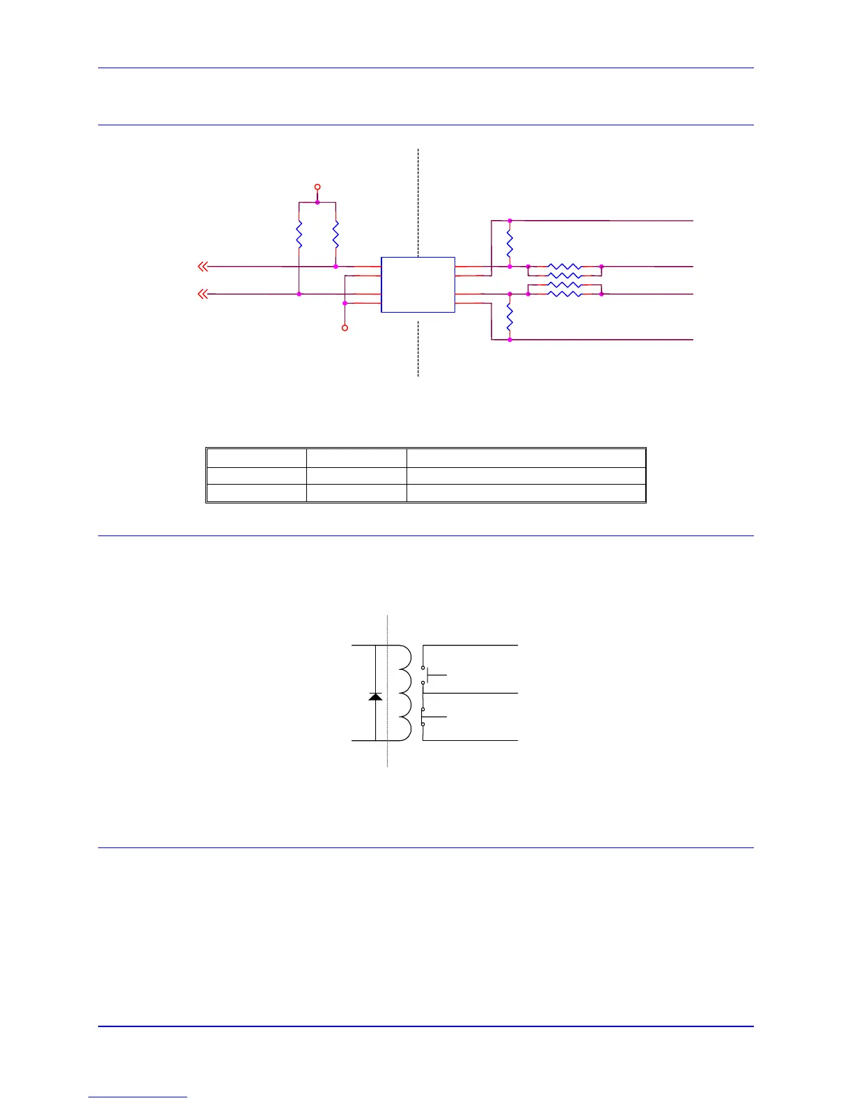
The amplifier fault circuit for the Acc-24E2A is functionally the same circuit as the limits and flag circuit.
FAULT_2
FAULT_2+
FAULT_2-
FAULT_1-
FAULT_1+
FAULT_1
FAULT_2
FAULT_1
R13
2.2K
"DGND" PLANE
U21
PS2705-2NEC-ND
1
27
8
3
45
6
CI1A
CI1BE1
C1
CI2A
CI2BE2
C2
R12
2.2K
RP36
4.7KSIP8I
1 2
3 4
5 6
7 8
"AGND" PLANE
R20
1K
R21
1K
GND
+5V
For single-ended amplifier fault inputs, typically the AFAULT+ would be the actual signal input from the
amplifier and the AFAULT- can be considered the reference.
Single Ended Amplifier Fault Inputs
AFAULT+ AFAULT- Input Type
0V +12V to 24V Sinking – Low True
12V to 24V 0V Sourcing – High True
Amplifier Enable Circuit
Most amplifiers have an enable/disable input that permit s complete shutdown of the amplifier regardless
of the voltage of the command signal. The Acc-24E2A AENA line is meant for this purpose. The
amplifier enable signals of the Acc-24E2A is controlled by a relay with normal opened and normal closed
dry contacts as shown in the diagram below:
AE_CO
M
AE_NO
AE_NC
5V+
AENA
Isolation
Loss of Encoder Circuit
The encoder-loss detection circuitry works for differential incremental encoders only. In proper operation,
the digital states of the complementary inputs for a channel (e.g. A and A/) always should be opposite:
when one is high, the other is low. If for some reason, such as a cable connection coming undone, one or
more of the signal lines is no longer driven, pull-up resistors on the input line pull and hold the signal high.
The encoder-loss detection circuitry uses exclusive-or (XOR) gates on each complementary pair to detect
whether the signals are in the same or opposite states. These results are combined to produce a single
encoder-loss status bit that the processor can read.
Hardware Setup 11