Accessory 24E2A
Resistor Pack Configuration
Differential or Single-Ended Encoder Selection
The differential input signal pairs to the PMAC have user-configurable pull-up/pull-down resistor
networks to permit the acceptance of either single-ended or differential signals in one setting, or the
detection of lost differential signals in another setting.
The ‘+’ inputs of each differential pair each have a hard-wired 1 kΩ pull-up resistor to +5V. This
cannot be changed.
•
• The ‘-’ inputs of each differential pair each have a hard-wired 2.2 kΩ resistor to +5V; also each has
another 2.2 kΩ resistor as part of a socketed resistor pack that can be configured as a pull-up resistor
to +5V, or a pull-down resistor to GND.
If this socketed resistor is configured as a pull-down resistor (the default configuration), the combination
of pull-up and pull-down resistors on this line acts as a voltage divider, holding the line at +2.5V in the
absence of an external signal. This configuration is required for single-ended inputs using the ‘+’ lines
alone; it is desirable for unconnected inputs to prevent the pick-up of spurious noise; it is permissible for
differential line-driver inputs.
If this socketed resistor is configured as a pull-up resistor (by reversing the SIP pack in the socket), the
two parallel 2.2 kΩ resistors act as a single 1.1 kΩ pull-up resistor, holding the line at +5V in the absence
of an external signal. This configuration is required if encoder-loss detection is desired; it is required if
complementary open-collector drivers are used; it is permissible for differential line-driver inputs even
without encoder loss detection.
If Pin 1 of the resistor pack (marked by a dot on the pack) matches Pin 1 of the socket (marked by a wide
white square solder pin on the front side of the board), then the pack is configured as a bank of pull-down
resistors. If the pack is reversed in the socket, it is configured as a bank of pull-up resistors.
The following table lists the pull-up/pull-down resistor pack for each input device:
Device Resistor Pack Pack Size
Encoder 1 RP22 6-pin
Encoder 2 RP24 6-pin
Encoder 3 RP22 6-pin
Encoder 4 RP24 6-pin
Termination Resistors Packs
The Acc-24E2A provides sockets for termination resistors on differential input pairs coming into the
board. As shipped, there are no resistor packs in these sockets. If these signals are brought long distances
into the Acc-24E2A board and ringing at signal transitions is a problem, SIP resistor packs may be
mounted in these sockets to reduce or eliminate the ringing.
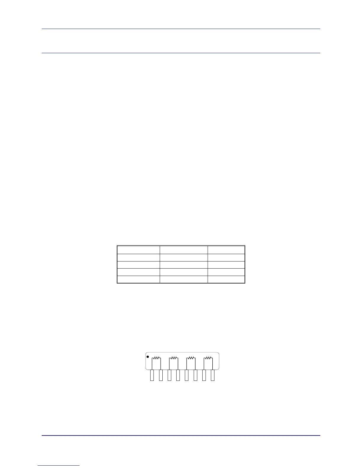
All termination resistor packs have independent resistors (no common connection) with each resistor
using two adjacent pins as shown below.
Isolated Resistor Network
1
Encoder Loss Resistor Packs
The Acc-24E2A also provides an encoder loss circuit to detect if the quadrature signals are valid. To
activate this feature, reverse the resistor pack from its default configuration.
8 Hardware Setup