Accessory 24E2A
Sample Wiring Diagrams
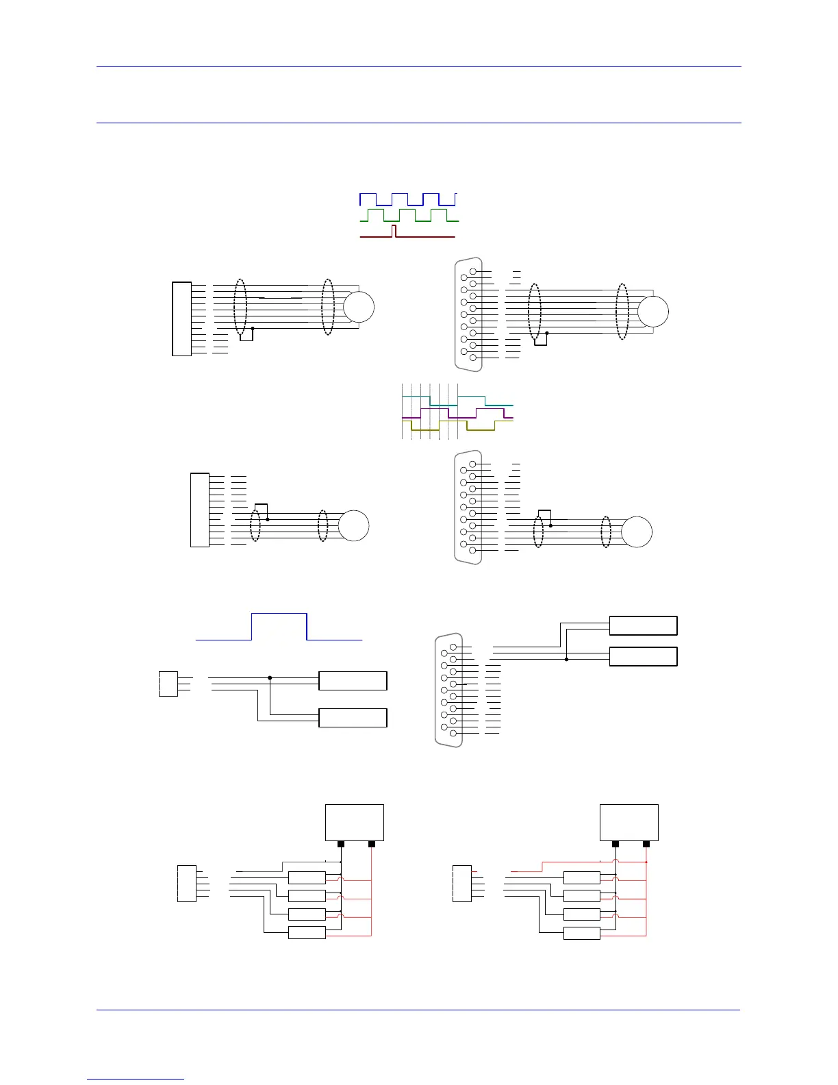
This section has typical wiring diagrams for the TTL level inputs, flags and limits, DAC and PFM outputs,
amplifier enable, and amplifier fault.
TTL Level Inputs and Outputs
1
2
3
4
5
6
7
8
9
10
11
12
A
A/
B
B/
C
C/
5V
GND
U
V
W
T
BEQU2
BEQU1
GND
A
A/
B
B/
C
C/
5V
GND
U
1
9
15
8
V
W
T
Shield
Quadrature Encoders
Encoder
Float Shield
Shield
Encoder
Float Shield
V
54 6 2 3 1
1
2
3
4
5
6
7
8
9
10
11
12
A
A/
B
B/
C
C/
5V
GND
U
V
W
T
Shield
BEQU2
BEQU1
GND
A
A/
B
B/
C
C/
5V
GND
U
1
9
15
8
V
W
T
TTL Hall Effect Sensors
Hall
Sensor
Float Shield
Shield
Hall
Sensor
Float Shield
U
W
3
2
1
GND
BEQU1
BEQU2
Output Device 1
Output Device 2
0 V
5 V
BEQU2
BEQU1
GND
A
A/
B
B/
C
C/
5V
GND
U
1
9
15
8
V
W
T
Output Device 2
Output Device 1
Position Compare Outputs
Position Limits, Home Flag, and User Flag
5
4
3
2
1
FLG_RTN_1
HOME1
MLIM1
PLIM1
USER1
Home
Neg
Pos
User
24V Supply
0V 24V
Acc-24E2A Sourcing Flags
5
4
3
2
1
FLG_RTN_1
HOME1
MLIM1
PLIM1
USER1
Home
Neg
Pos
User
24V Supply
0V 24V
Acc-24E2A Sinking Flags
16 Connections
 Loading...