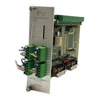
Accessory 24E2A
MLDT Feedback for UMAC-MACRO
The data from the MLDT is processed as a parallel word input at the MACRO Station and then
transmitted back to the Ultralite using the traditional Servo Node. The encoder conversion table at the
MACRO Station must be modified to process this data. From the Ultralite standpoint, nothing needs to
be modified to read the position and velocity data.
Since the data is also absolute, the data can also be sent at the Ultralite as absolute data for correct
position at power-up. This is accomplished with the proper setup of MSn,MI11x at the MACRO Station,
and Ix10 at the Ultralite or Ix10 and Ix95 with the Turbo Ultralite. Regardless of the type of Ultralite,
retrieving the power-on-position is the same. The information must be retrieved from MACRO Station
variable MSn,MI920 for each node transfer as specified by Ix10 at the Ultralite. MSn,MI920 does not
need to be set up because the MACRO Station will place the power-on position the appropriate register at
power-up.
MLDT Software Setup of the UMAC MACRO
When the Acc-24E2A is used for MLDT feedback in a UMAC MACRO system, there are a few MI-
variables in the MACRO Station, and a few in the PMAC2 or Turbo PMAC2 driving the Station, that
must be set up properly.
Station Hardware Setup I-Variables for Servo IC
MS{anynode},MI903/MI907 (PFM Clock Frequency): In almost all cases, the clock frequency driving
the pulse-generation circuitry for all channels on the Servo IC can be left at its default value of 9.83 MHz
(0.102 µsec). Few will need to change MI903/MI907, which also controls other clock signals, from its
default value of 2258.
MS{anynode},MI904/MI908 (PFM Pulse Width): The pulse width, set by MI904/MI908 in units of
PFM clock cycles must be set long enough for the MLDT to see, and long enough to contain the rising
edge of the RPM start echo pulse, or the rising edge of the single DPM echo pulse. For example, if this
edge can come up to 2 µsec after the start of the excitation pulse, and the PMAC clock cycle is at its
default of about 0.1 µsec, then I7m04 must be set at least to 20.
MS{node},MI916 (Output Format Select): For the channel associated with this node to be used for
MLDT feedback, MI916 must be set to 1 or 3 for the C sub-channel to be used for PFM-format output.
On an Acc-24E2A, I7mn6 must then be set to 3 for the A and B sub-channels to be used for DAC-format
output.
MS{node},MI910 (MLDT Feedback Select): For the channel associated with this node to be used for
MLDT feedback, MI910 must be set to 12. In this mode, the pulse timer is cleared on the output pulse,
and latched on the echo pulse, counting in between at 117.96 MHz.
Station Conversion Table Processing I-Variables
The pulse timer for Servo IC m Channel n holds a number proportional to the time and therefore the
position. This must be processed in the conversion table before it can be used by the servo loop. It is best
to use the filtered parallel data conversion, a 3-line entry in the table (three consecutive MI-variables.
The MI-variables for the conversion table start at MI120.
Line 1 (Method and Address): This 24-bit value (6 hex digits) should begin with a 3 (filtered parallel
data) followed by the address of the timer register. The possible values for this line are shown in the
following table:
MLDT Feedback for UMAC-MACRO 35