Accessory 24E2A
Encoder Conversion Table I-Variables
To use feedback or master position data from an Acc-24E2, add entries to the encoder conversion table
(ECT) using I-variables I8000 – I8191 to address and process this data. The default conversion table in
the Turbo PMAC does not contain these entries; it only contains entries for the eight channels on board
the Turbo PMAC.
Usually, the position data obtained through an Acc-24E2 board is an incremental encoder feedback, and
occasionally an A/D converter feedback from an Acc-28E board or Acc-36E.
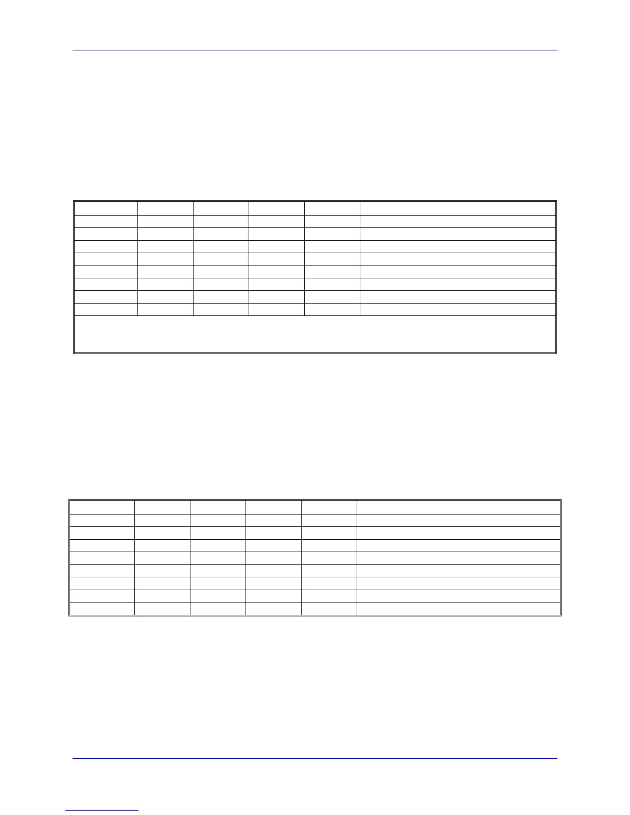
The ECT entries for Acc-24E2 incremental encoder channels are shown in the following table:
Servo IC # Chan. 1 Chan. 2 Chan. 3 Chan. 4 Notes
2 $m78200 $m78208 $m78210 $m78218 First Acc-24E2x Channel n Encoder Set
3 $m78300 $m78308 $m78310 $m78318 Second Acc-24E2x Channel n Encoder Set
4 $m79200 $m79208 $m79210 $m79218 Third Acc-24E2x Channel n Encoder Set
5 $m79300 $m79308 $m79310 $m79318 Fourth Acc-24E2x Channel n Encoder Set
6 $m7A200 $m7A208 $m7A210 $m7A218 Fifth Acc-24E2x Channel n Encoder Set
7 $m7A300 $m7A308 $m7A310 $m7A318 Sixth Acc-24E2x Channel n Encoder Set
8 $m7B200 $m7B208 $m7B210 $m7B218 Seventh Acc-24E2x Channel n Encoder Set
9 $m7B300 $m7B308 $m7B310 $m7B318 Eighth Acc-24E2x Channel n Encoder Set
The first hexadecimal digit in the entry, represented by m in the table, is a 0 for the most common 1/T timer-
based extension of digital incremental encoders; it is an 8 for the parallel-data extension of analog incremental
encoders; it is a C for no extension of an incremental encoder.
Motor Addressing I-Variables
For a Turbo PMAC motor to use the servo interface circuitry of the Acc-24E2, several of the addressing I-
variables for the motor must contain the addresses of registers in the Acc-24E2, or the addresses of encoder
conversion table registers containing data processed from the Acc-24E2. These I-variables can include:
Ixx02: Motor xx Command Output Address
Ixx02 tells Turbo PMAC where to write its command outputs for Motor xx. If Acc-24E2 is to create the
command signals, Ixx02 must contain the address of the register.
The following table shows the address of the A output register for each channel of each Acc-24E2. These
addresses can be used for single analog outputs, double analog outputs, or direct PWM outputs.
Servo IC # Chan. 1 Chan. 2 Chan. 3 Chan. 4 Notes
2 $078202 $07820A $078212 $07821A First Acc-24E2x Channel n DAC/PWMnA
3 $078302 $07830A $078312 $07831A Second Acc-24E2x Channel n DAC/PWMnA
4 $079202 $07920A $079212 $07921A Third Acc-24E2x Channel n DAC/PWMnA
5 $079302 $07930A $079312 $07931A Fourth Acc-24E2x Channel n DAC/PWMnA
6 $07A202 $07A20A $07A212 $07A21A Fifth Acc-24E2x Channel n DAC/PWMnA
7 $07A302 $07A30A $07A312 $07A31A Sixth Acc-24E2x Channel n DAC/PWMnA
8 $07B202 $07B20A $07B212 $07B21A Seventh Acc-24E2x Channel n DAC/PWMnA
9 $07B302 $07B30A $07B312 $07B31A Eighth Acc-24E2x Channel n DAC/PWMnA
If the C output register for a given Acc-24E2 and channel is used (primarily for pulse and direction
output), simply add 2 to the address shown in the above table. For example, on the first Acc-24E2, output
register 1C is at address $078204.
Ixx03: Motor xx Position-Loop Feedback Address
Ixx04: Motor xx Velocity-Loop Feedback Address
UMAC Software Setup 23
 Loading...