Accessory 24E2A
Line 1 (Method and Address): This 24-bit value (6 hex digits) should begin with a “3” (filtered parallel
data) followed by the address of the timer register. The possible values for this line are shown in the
following table:
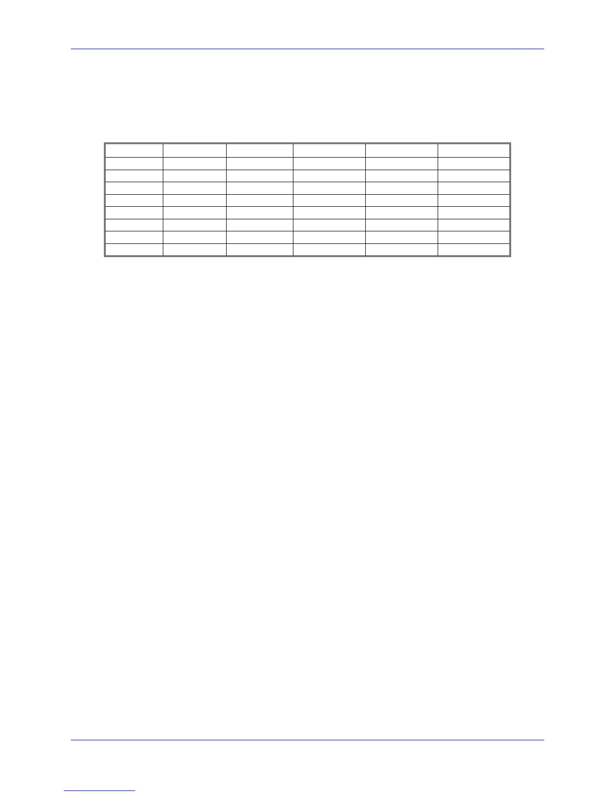
Encoder Conversion Table Parallel Filtered Data Format First Line for Acc-24E2A Boards with
Servo IC m Channel n
Acc-24 # Servo IC # Channel 1 Channel 2 Channel 3 Channel 4
1A 2 $378200 $378208 $378210 $378218
1B 3 $378300 $378308 $378310 $378318
2A 4 $379200 $379208 $379210 $379218
2B 5 $379300 $379308 $379310 $379318
3A 6 $37A200 $37A208 $37A210 $37A218
3B 7 $37A300 $37A308 $37A310 $37A318
4A 8 $37B200 $37B208 $37B210 $37B218
4B 9 $37B300 $37B308 $37B310 $37B318
Line 2 (Width and Start): This 24-bit value should be set to $013000 to specify the use of 19 bits
($013) starting at bit 0.
Line 3 (Max Change): This 24-bit value should be set to a value slightly greater than the maximum true
velocity ever expected, expressed in timer LSBs per servo cycle. With a typical MLDT, the 117.96 MHz
timer LSB represents 0.024 mm (0.00094 inches); the default servo cycle is 0.442 msec.
The result of this conversion is in the X-register of the third line. Any functions using this value should
address this register. For example, if this were the first entry in the table, which starts at $003501, the
result would be in X:$003503.
Motor I-Variables
Ixx03 (Position Loop Feedback Address): To use the result of the conversion table for position-loop
feedback for Motor xx, Ixx03 should contain the address of the result register in the conversion table -
$003503 in the above example.
Ixx04 (Velocity Loop Feedback Address): To use the result of the conversion table for velocity-loop
feedback for Motor xx, Ixx04 should contain the address of the result register in the conversion table -
$003503 in the above example.
Ixx05 (Master Position Address): To use the result of the conversion table for the master position for
Motor xx, Ixx05 should contain the address of the result register in the conversion table - $003503 in the
above example.
Ixx10 and Ixx95 (Power-On Position Address and Format): To use the MLDT for absolute power-on
position for Motor xx, Ixx95 should be set to $180000 (up to 24 bits of parallel Y-data) and Ixx10 should
be set to the address of the timer register used:
32 MLDT Feedback for UMAC-MACRO