Accessory 24E2A
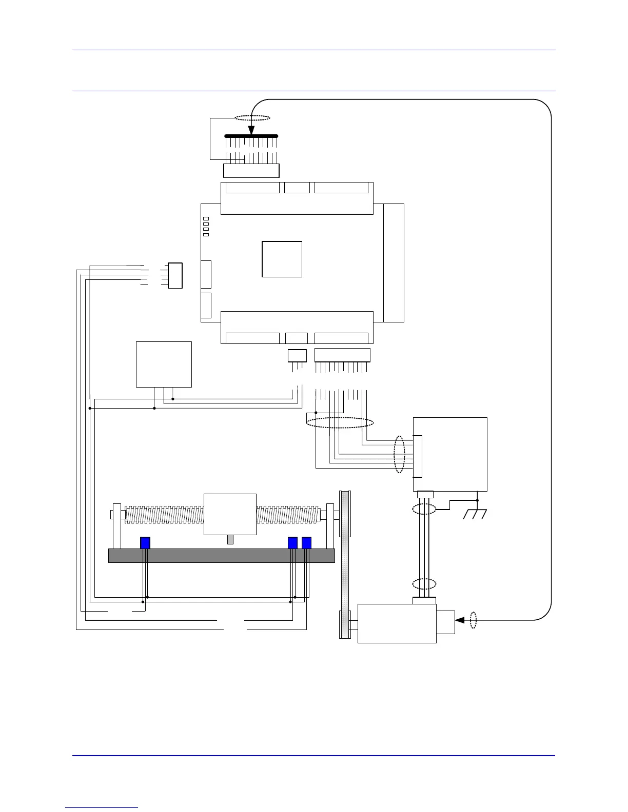
Overall Wiring Diagram
FLG_RTN
Servo Motor
LOAD
Amplifier
TB1
Front
TB1 Top
TB1 Bottom
T
W
V
U
GND
5V
C/
C
B/
B
A/
A
+/- 15V
Supply
12 11 10 9 8 7 6 5 4 3 2 1
AAGND
AA+15V
AFAULT-
AFAULT+
AE_NO
AE_COM
AE_NC
DAC1B-
DAC1B+
DAC1A-
DAC1A+
12 11 10 9 8 7 6 5 4 3 2 1
3 2 1
A
A
G
N
D
A
A
-
1
5
V
Float Shield
Float
Shield
Shield
Float Shield
54 3 2 1
PLIM
MLIM
HOME
USER
y
y
y
Pos Limit
Home Flag
Neg Limit
GND +15V-15V
Shield
*Remove E85, E87, and E88
for External Power Supply
Acc-24E2A
This is a general example of a system with sourcing flags and normally open amplifier
enable output from the Acc-24E2A. For opto-isolation an external power supply is
used and E85, E87, and E88 have been removed from the Acc-24E2A.
15V
AGND
Pin#2
Pin#3
Connections 15