Chapter 4 Installation and Wiring
4-33
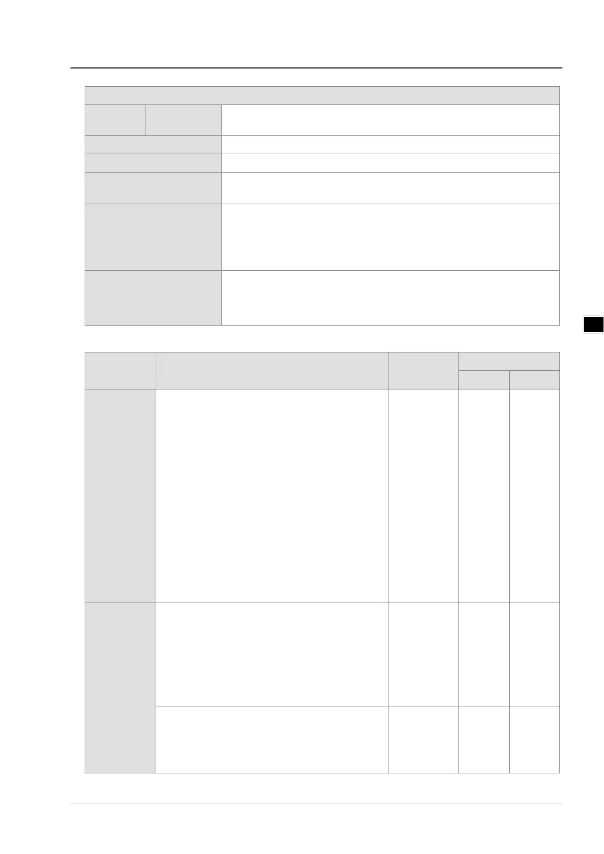
Output
Servo output
Y0.0+, Y0.0-, Y0.2+, Y0.2-, Y0.1+, Y0.1-, Y0.3+, Y0.3-, Y0.8, and Y0.9
External communication port
Number of basic instructions
Number of applied
instructions
130
M-code
1. OX0~OX99 (motion subroutine/positioning program): M02 (The execution
of the program stops. (END))
2. M00~M01, M03~M101, and M103~M65535:
The execution of the program pauses. (WAIT)
G-code
G0 (rapid positioning), G1 (linear interpolation), G2 (circular interpolation,
clockwise), G3 (circular interpolation, counterclockwise), G4 (dwell), G17 (XY
plane selection), G90 (absolute programming), and G91 (incremental
Description of the terminals
Terminal Description
Response
characteristic
X0.0, X0.1,
X0.8, X0.9,
X0.12, and
X0.13
1. Single/A/B-phase input terminals.
2. The functions of the terminals:
Motion control:
X0.0 is the PG input for axis 1, and X0.1 is
the PG input for axis 2.
X0.12 is the DOG input for axis 1, and
X0.13 is the DOG input for axis 2.
X0.8 and X0.9 are for a manual pulse
generator.
High-speed count:
X0.0 is the RESET input for counter 0.
X0.8 is the A-phase input for counter 0,
and X0.9 is the B-phase input for counter
0.
High-speed capture
: The terminals can function
as trigger signals for high-speed capture.
Interrupt input s: X0.8, X0.9, X0.12, X0.13
100 kHz (*1) 5 mA 24 V
Y0.8 and Y0.9
1. The high-speed pulse output terminals are
transistors whose collectors are open collectors.
2. The functions of the terminals:
Motion control: Y0.8 is the CLEAR output for
axis 1, and Y0.9 is the CLEAR output for axis 2.
High-speed comparison: The high-speed
comparison output teminals provide the PWM
200 kHz 15 mA 24 V
Y0.1+, Y0.1-,
Y0.2+, Y0.2-,
Y0.3+, and
1. Differential output terminals.
2. The function of the terminals:
Motion control:
Y0.0+ and Y0.0- are the A-phase output
terminals for axis 1. Y0.2+ and Y0.2- are
1 MHz 5 mA 5 V
 Loading...


