AH Motion – Hardware Manual
4-36
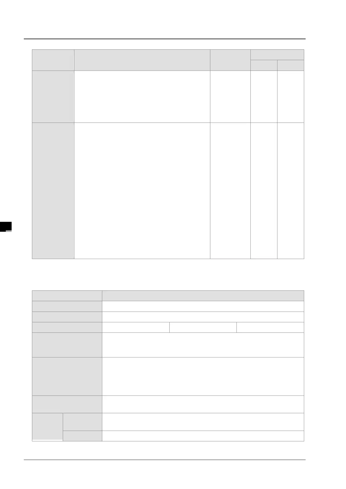
Terminal Description
Response
characteristic
output for axis 5, and Y0.10 is the A-phase
output for axis 6. Y0.9 is the B-
for axis 5, and Y0.11 is the B-phase output
for axis 6.
High-speed compariso: The terminals can
function as high-speed comparison output
Y0.0+, Y0.0-,
Y0.1+, Y0.1-,
Y0.2+, Y0.2-,
Y0.3+, Y0.3-,
Y0.4+, Y0.4-,
Y0.5+, Y0.5-,
Y0.6+, Y0.6-,
Y0.7+, and
Y0.7-
1. Differential output terminals.
2. The function of the terminals:
Motion control:
The terminals are for axis 1~axis 4.
Y0.0+ and Y0.0- are the A-phase output
terminals for axis 1. Y0.2+ and Y0.2-
A-phase output terminals for axis 2. Y0.4+
and Y0.4- are the A-phase output terminals
for axis 3. Y0.6+ and Y0.6- are the A-phase
output terminals for axis 4.
Y0.1+ and Y0.1- are the B-phase output
terminals for axis 1. Y0.3+ and Y0.3-
B-phase output terminals for axis 2. Y0.5+
and Y0.5- are the B-phase output terminals
for axis 3. Y0.7+ and Y0.7- are the B-phase
output terminals for axis 4.
Y0.0+ and Y0.0- are the CLEAR output
terminals for axis 5. Y0.1+ and Y0.1-
are the
CLEAR output terminals for axis 6.
1 MHz 5 mA 5 V
*1. If the frequency of input signals received by an input terminal must achieve 200 kHz, the input terminal must be
connected to a 1 kΩ (2 W) resistor in parallel.
AH15PM-5A
The capacity of the built-in storage is 64K steps.
Connection with a CPU
module
You can set the initial register involved in the data exchange in a CPU module, and
the number of registers involved in the data exchange in the CPU module. Four
hundred data registers at most can be involved in the data exchange.
Motor control
Ther
e are three types of pulse output modes. These modes adopt the differential
output.
1. Pulse/Direction
2. Counting up/Counting down
Maximum speed
Single axis: 1M PPS
Multi-axis interpolation: 1M PPS
Input
signal
Operating
STOP/RUN (automatic/manual switch)
X0.0+, X0.0-, X0.1+, X0.1-, X0.2+, X0.2-, X0.3+, X0.3-, X0.4, X0.5, X0.6, X0.7,
 Loading...


