Chapter 4 EIP Builder
4-23
4.4 Data Mapping
When the connection between devices is established, users can use the data mapping function to exchange
data between devices. This section will provide an overview of how to create a data mapping table.
Download
Data Exchange
Data Exchange
Set up
Data Exchange
Table
Network View
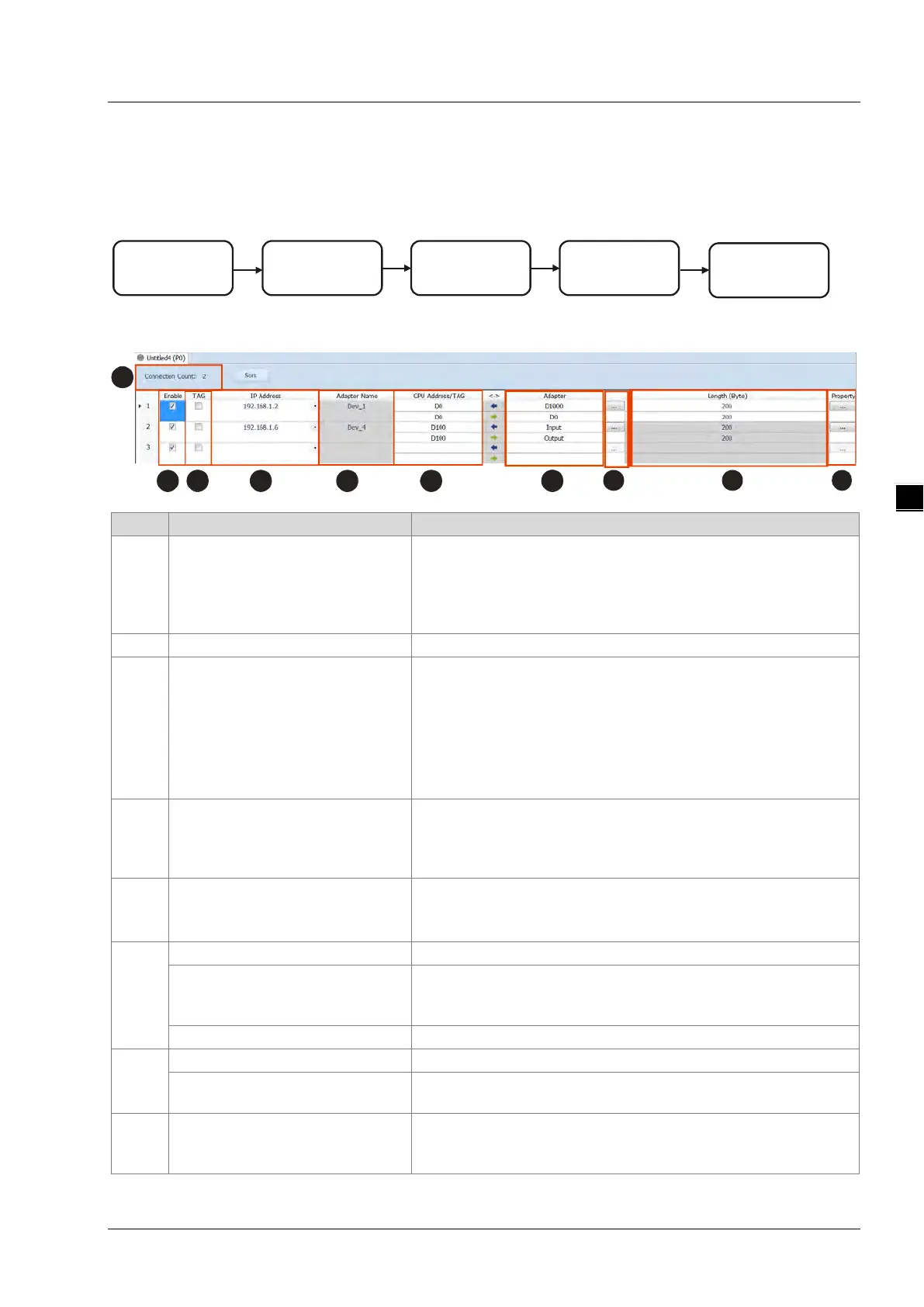
Descriptions for the Data Mapping:
Connection Count
Data mapping connection count; each row represents one
independent EtherNet/IP connection. The number of connections
cannot exceed the maximum connection number that the Scanner
supports. For the AH10EN-5A series, the maximum connection
Enable / Disable the data mapping function
TAG
Use TAGs created to execute data mapping; after selected, this
function is enabled and
read only ()
registers are not available for the row selected
the leghth cannot be modified
comsumed TAG should be created in ISPSoft global symbols
IP Address
The IP address of the Adapter that you’d like to connect to. After the
data mapping connection is established, the system will load the
connected device’s IP address. Users can also use the drop down list
to select the device’s IP address to add and edit the connection.
Adapter Name
Once the IP address is selected, its name will be displayed but cannot
be modified here. Refer to section 4.3 for more information on
how to change the device name.
Start address of the data mapping’s register
Scanner’s register address +
address offset (EtherNet/IP
Actual represented register = starting register address + address
offset; starting register address can be set on the HWCONFIG setup
Consumed TAG can be selected from the drop-down list
Adapter Address/Parameter
Target adapter’s register address / parameters
If TAG is selected
Input the Produced TAG of the EIP to be connected; the default name
I/O Mapping Table
Set up the IN/OUT parameters; when there is no I/O representative
table presented for the Adapter, they cannot be opened, for example
some PLCs.
 Loading...