Chapter 2 Installation and Wiring
VFD-EL-W
2-4
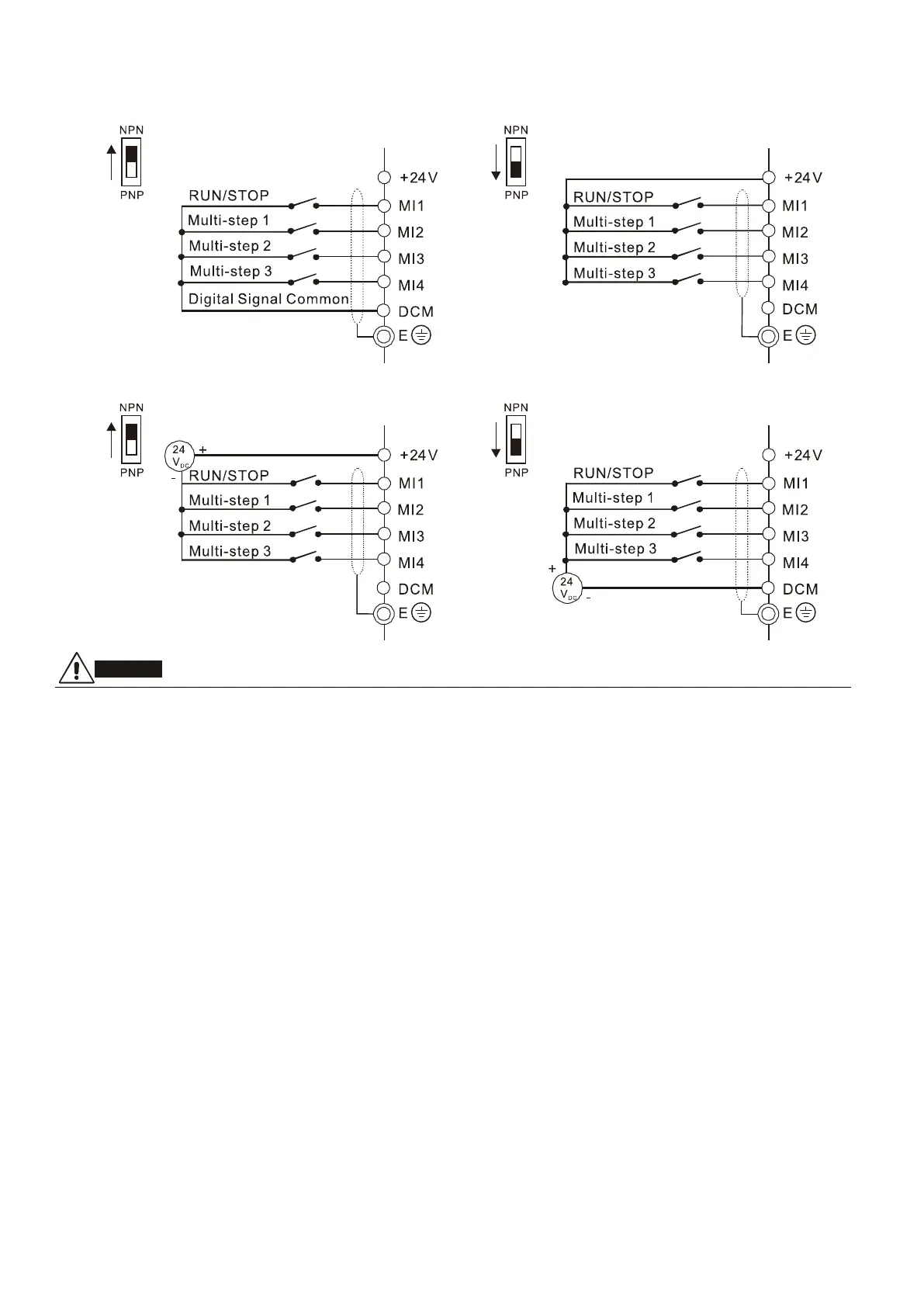
Wiring for NPN and PNP mode
Internal power supply
External power supply
1. Separate the main circuit and control circuit wiring to prevent erroneous actions.
2. Use shielded wire for the control wiring and do not expose the peeled-off shield in front of the terminal.
3. Use shielded wire or conduit for the power wiring and ground the two ends of the shielded wire or conduit.
4. Damaged insulation of wiring may cause personal injury or damage to circuits and equipment if it comes in
contact with high voltage.
5. The AC motor drive, motor and wiring may cause interference. To prevent equipment damage, take care of
interference between the surrounding sensors and the equipment.
6. Connect the AC drive output terminals U/T1, V/T2, and W/T3 to the motor terminals U/T1, V/T2, and W/T3,
respectively. To permanently reverse the direction of motor rotation, switch over any of the two motor leads.
7. With long motor cables, high capacitive switching current peaks can cause over-current, high leakage current
or lower current readout accuracy. To prevent this, the motor cable should be less than 20 m for 4.0 kW
models and below. The cable should be less than 50 m for 5.5 kW models and above. For longer motor
cables, use an AC output reactor.
8. The AC motor drives, electric welding machines and the larger horsepower motors should be grounded
separately.
9. Use ground leads that comply with local regulations and keep them as short as possible.
10. The VFD-EL-W series does not have a built-in brake unit,and no support for external brake unit and brake
resistor.
11. When grounding, choose wires that comply with local regulations for your safety.
12. To prevent lightning strike and electric shock, the metal grounding wire of electrical equipment should be
thick and short, and connected to the dedicated grounding terminal of the inverter system.
13. You can install multiple VFD-EL-W units in one location. All the units should be grounded directly to a
common ground terminal, as shown in the figure below. Ensure that there are no ground loops.
 Loading...