-LA-3500
24
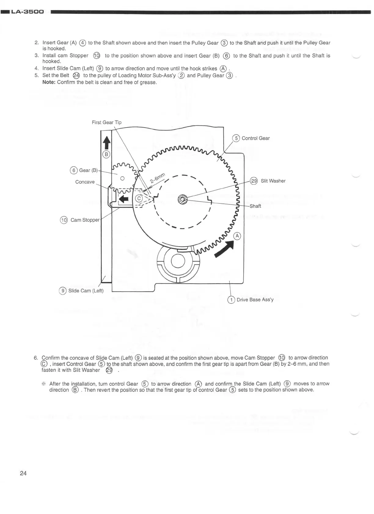
2.
Insert Gear
(A)
@ to the Shaft shown above and then insert the Pulley Gear @
to
the Shaft and push
it
until the Pulley Gear
is
hooked.
3.
Install cam Stopper @ to the positi
on
shown above and insert Gear (8) @ to the Shaft and push
it
until the Shaft is
hooked.
4.
Insert Slide Cam (Left) ®
to
arrow direction and
move
until the hook strikes @ .
5. Set the Belt @
to
the pulley of Loading Motor Sub-Ass'y @ and Pulley Gear @ .
Note: Confirm the belt
is
clean and free of grease.
First Gear
Tip
t
@ Control Gear
®
@ Gear (
B)
Concave
@ Slit
Washer
@
Cam
Stopper
@
Slide
Cam
(Left)
Cl)
Drive
Base
Ass
'y
6.
Confirm the concave of Slide Cam (Left) ®
is
seated at the position shown above,
move
Cam Stopper @ to arrow direction
© , insert Control Gear
®to
the shaft shown above, and confirm the first gear tip
is
apart from Gear (8)
by
2-6
mm, and then
fasten it with Slit Washer @ .
7l
7 After the installation, turn control Gear
@)
to arrow direction @ and confirm the Slide Cam (Left) ® moves
to
arrow
direction @ . Then revert the position
so
that the first gear tip of control Gear @ sets
to
the position shown above.


 To Next Page