.............................................................................
LA-3500
..
Initial
Mode
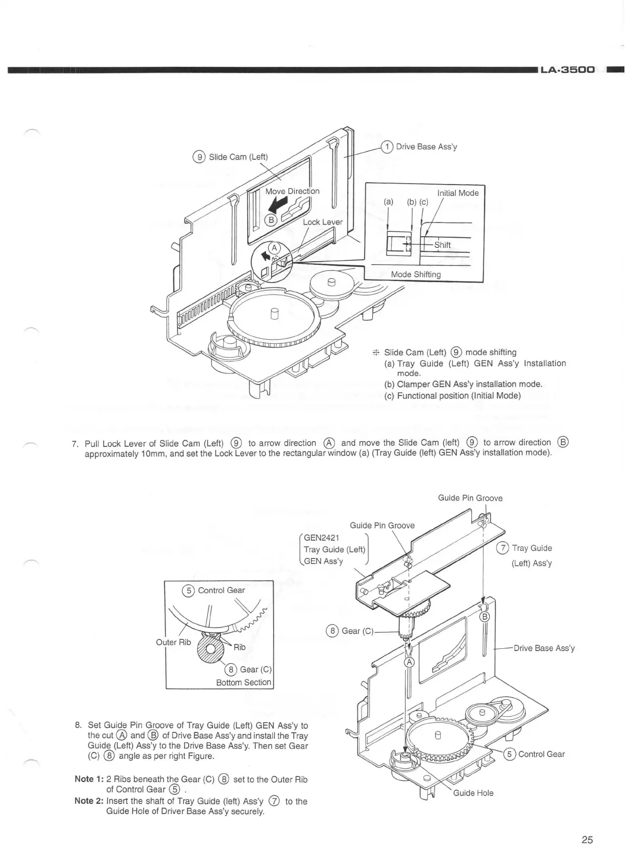
* Slide Cam (Left) ® mode shifting
(a)
Tray Guide (Left) GEN Ass'y Installation
mode.
(b}
Clamper GEN Ass'y installation mode.
(c)
Functional position (Initial Mode)
7.
Pull Lock Lever of Slide Cam (Left) ®
to
arrow direction @ and move the Slide Cam (left) ® to arrow direction @
approximately 1
Omm,
and set the Lock Lever
to
the rectangular window
(a)
(Tray Guide (left) GEN Ass'y installation mode).
8.
Set Guide Pin Groove of Tray Guide (Left) GEN Ass'y
to
the
cut@
and @ of Drive Base Ass'y and install the Tray
Guide (Left) Ass'y to the Drive Base Ass'y. Then set Gear
(C)
@ angle as per right Figure.
Note
1:
2 Ribs beneath the Gear
(C)
@ set to the Outer Rib
of Control Gear ® .
Note 2: Insert the shaft of Tray Guide (left) Ass'y (j)
to
the
Guide Hole of Driver Base Ass'y securely.
Guide
Pin
Groove
(V
Tray
Guide
(Left)
Ass
'y
Drive
Base
Ass
'y
25


 To Next Page