SIRIUS®
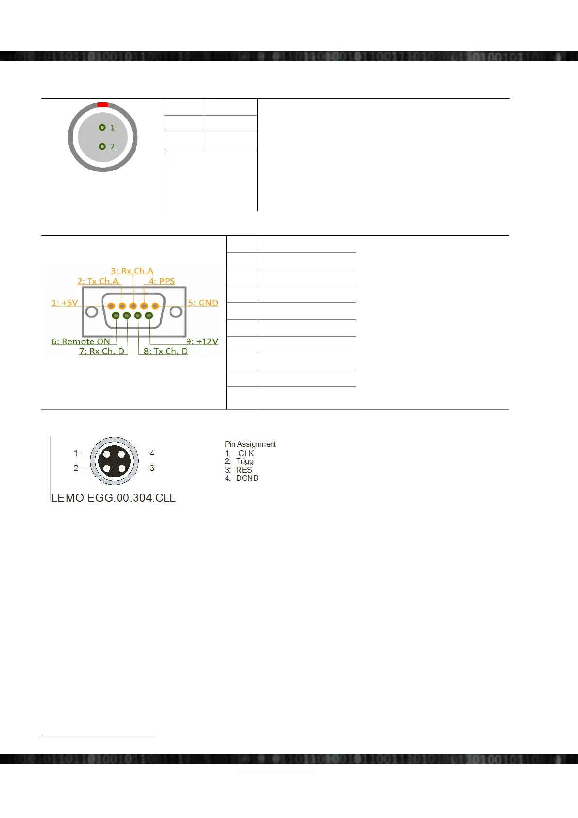
4.7.3.1 Power connector
Illustration 78:
Power Connector 2pin
Pin Name L2B2f
Power connector (on the S-BOX): ECG.2B.302
Mating connector (for the cable): FGJ.2B.302
1 V+
2 GND
4.7.3.2 Option: GPS connector
Illustration 79: GPS Connector
Pin Name
To power the system on, press the
Power switch OR apply a voltage
between 3 and 30V to Remote-On pin
To power off the system press the
Power switch or reduce the voltage
on Remote-On below 0.5V for more
than one second.
GPS port A is used for GPS-Display
or for the RF-modem when RTK
option is in use.
GPS port D is reserved. Do not
connect!
1 +5V (max. 0.5A)
2 TXD GPS port A
3 RXD GPS port A
4 GPS PPS
5 GND
6 Remote-On
7
7 RXD GPS port D
8 TXD GPS port D
9 +12V (max. 0.5A)
4.7.3.3 Sync connectors: Pin-out (LEMO 4pin)
Illustration 80: SIRIUS Sync connector: pin-out (LEMO
4pin)
Mating connector: FGG.00.302.CLAD27Z
When IRIG-synchronisation is used, the IRIG signal is
on pins 1, 2.
Since there are 2 connectors it's easy to chain several SIRIUS® chassis (or DEWE-43, DS-CAN2, etc.) together.
Note that there is no distinction between IN and OUT – it does not matter which connector you use.
7 Remote-On may not be available for units before Q1/2013
Page 42/166 www.dewesoft.com Doc-Version: 1.4.2