Micronics C400 System Board Manual
Chapter 2: Configuring the Micronics C400
13
Jumper and Connector Settings
This section provides jumper and connector settings for the Micronics
C400 system board that may or may not need to be changed. Other
configurations can be changed through the BIOS Setup.
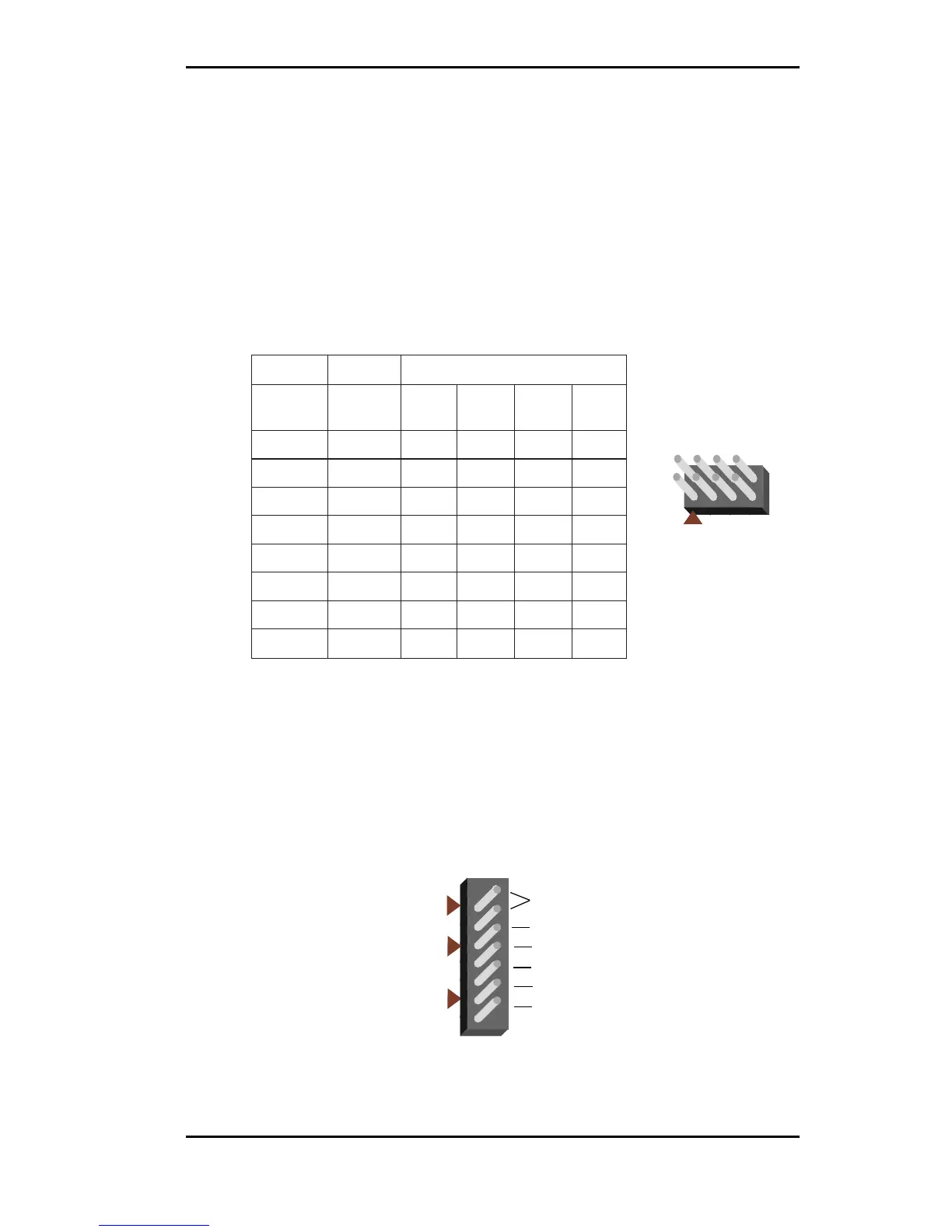
Table 2-1 lists the jumper settings to select the CPU bus speed frequency.
Table 2-2 lists the settings for clearing a password, locking your case and
the power LED. To clear a password set in the BIOS, place a jumper on JP1.
The Power LED is the same as the Power LED in the Front Panel
connectors.
Table 2-1: CPU Speed Selection
2PJrepmuJ
metsyS
deepS
suB
deepS
2-14-36-58-7
332
zHM
zHM66nepO
esolC
nepOesolC
662
zHM
zHM66
esolC
nepO
esolC
esolC
03
zHM0
zHM66
esolC
nepOnepOesolC
333
zHM
zHM66nepOnepOesolCesolC
003
zHM
zHM001nepOesolCesolCesolC
53
zHM0
zHM001nepOesolCnepOesolC
004
zHM
zHM001
esolCnepO
esolCesolC
54
zHM0
zHM001esolCnepOnepOesolC
2
1
JP2
8
7
Table 2-2: Clear Password/Key Lock/Power LED Settings
Clear
Password
LED -
N/A
LED +
Ground
Keylock
Keylock
Power
LED
JP1
J17