Analog and digital I/O lines I/O Configuration
XBee/XBee-PRO® S2C ZigBee® RF Module
145
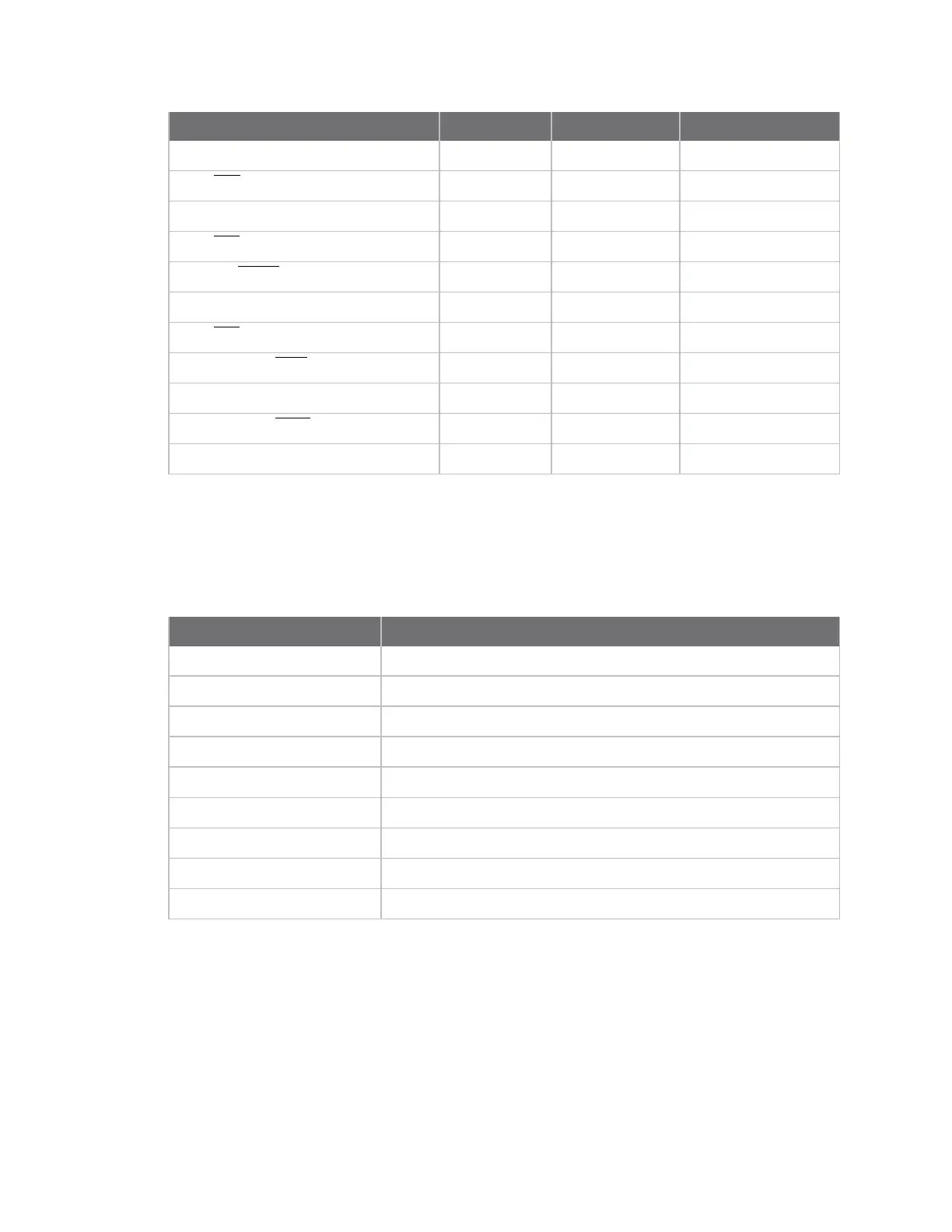
Module Pin Names Module Pin AT Command Command Range
DIO11/PWM1/DAC1 7
P1
0, 1, 3-5
DIO8/DTR/SLP_RQ
9
D8
0, 1, 3-5
DIO4/SPI_MOSI 11
D4
0, 1, 3-5
DIO7/CTS
12
D7
0, 1, 3-7
DIO9/On/SLEEP/SWO
13
D9
0, 1, 3-5
DIO5/ASSOC/JTDI 15
D5
0, 1, 3-5
DIO6/RTS
16
D6
0, 1, 3-5
DIO3/AD3/SPI_SSEL
17
D3
0-5
DIO2/AD2/SPI_SCLK 18
D2
0-5
DIO1/AD1/SPI_ATTN
19
D1
0-6
DIO0/AD0/CommBtn 20
D0
0-5
I/O Configuration
To enable an analog or digital I/O function on one or more XBee/XBee-PRO ZigBee RF Module pin, you
must issue the appropriate configuration command with the correct parameter. After issuing the
configuration command, you must apply changes on the device for the I/O settings to take effect.
Pin command parameter Description
0 Disabled (see the information following the table)
1 Peripheral control
2 Analog
3 Data in monitored (see the information following the table)
4 Data out default low
5 Data out default high
6 RS485 enable low / packet trace interface
7 RS485 enable high
>7 Unsupported
When the pin command parameter is a 0 or a 3, it operates the same on this platform, except the
device does not monitor the pin by I/O sampling if the parameter is 0.
Inputs have three variations:
n floating
n pulled-up
n pulled-down