Technical specifications Hardware specifications for the programmable variant
XBee/XBee-PRO® S2C ZigBee® RF Module
20
GPIO electrical specification Value
Low Schmitt switching threshold 0.42 - 0.5 x VCC
High Schmitt switching threshold 0.62 - 0.8 x VCC
Input current for logic 0 -0.5 µA
Input current for logic 1 0.5 µA
Input pull-up resistor value
29 kΩ
Input pull-down resistor value
29 kΩ
Output voltage for logic 0 0.18 x VCC
(maximum)
Output voltage for logic 1 0.82 x VCC
(minimum)
Output source/sink current for pad numbers 3, 4, 5, 10, 12, 14, 15, 16, 17, 25, 26,
28, 29, 30, and 32 on the SMT modules
4 mA
Output source/sink current for pin numbers 2, 3, 4, 9, 12, 13, 15, 16, 17, and 19 on
the TH modules
4 mA
Output source/sink current for pad numbers 7, 8, 24, 31, and 33 on the SMT
modules
8 mA
Output source/sink current for pin numbers 6, 7, 11, 18, and 20 on the TH modules 8 mA
Total output current (for GPIO pads) 40 mA
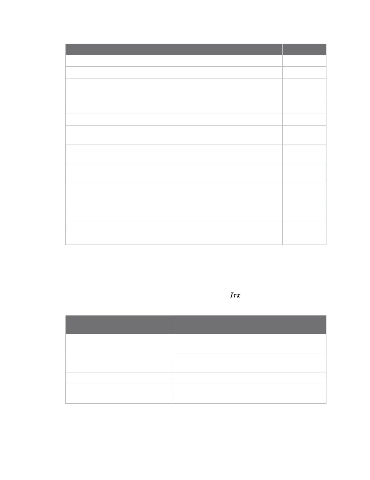
Hardware specifications for the programmable variant
If the module has the programmable secondary processor, add the following table values to the
specifications listed. For example, if the secondary processor is running at 20 MHz and the primary
processor is in receive mode then the new current value will be Itotal = Ir2 + Irx = 14 mA + 9 mA = 23 mA,
where Ir2 is the runtime current of the secondary processor and is the receive current of the
primary.
Optional secondary processor
specification
Add to RX, TX, and sleep currents specifications
depending on mode of operation
Runtime current for 32 k running at 20
MHz
+14 mA
Runtime current for 32 k running at 1
MHz
+1 mA
Sleep current
+0.5 µA typical
For additional specifications see NXP
Datasheet and Manual
MC9S08QE32