AT commands I/O settings commands
XBee/XBee-PRO® S2C ZigBee® RF Module
247
If LT = 0, the device uses the default blink rate: 500 ms for a sleep coordinator, 250ms for all other
nodes.
For all other LT values, the firmware measures LT in 10 ms increments.
Parameter range
0, 0x0A - 0xFF (100 - 2550 ms)
Default
0
PR (Pull-up/Down Resistor Enable)
The bit field that configures the internal pull-up/down resistor status for the I/O lines. If you set a PR
bit to 1, it enables the pull-up/down resistor; 0 specifies no internal pull-up/down resistor. The
following table defines the bit-field map for PR command.
PR and PD only affect lines that are configured as digital inputs or disabled.
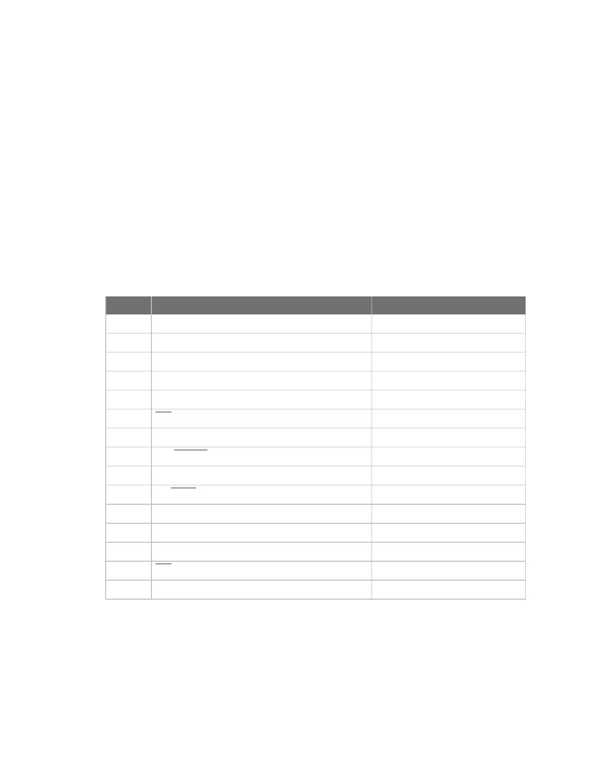
The following table defines the bit-field map for PR and PD commands.
Bit I/O line Module pin
0 DIO4 24/SMT, 11/TH
1 AD3/DIO3 30/SMT, 17/TH
2 AD2/DIO2 31/SMT, 18/TH
3 AD1/DIO1 32/SMT, 19/TH
4 AD0/DIO0 33/SMT, 20/TH
5
RTS/DIO6
/SMT, 16/TH
6 DTR/SLEEP_REQUEST 10/SMT, 9/TH
7
DIN/CONFIG
4/SMT, 3/TH
8 ASSOCIATE/DIO5 28/SMT, 15/TH
9
On/SLEEP/DIO9
26/SMT, 13/TH
10 DIO12 5/SMT, 4/TH
11 PWM0/RSSI/DIO10/ 7/SMT, 6/TH
12 PWM1/DIO11 8/SMT, 7/TH
13
CTS/DIO7
25/SMT, 12/TH
14 DOUT/DIO13 3/SMT, 2/TH
Parameter range
0 - 0x7FFF (bit field)
Default
0x1FFF