Page -9Digital Dream Standalone Motion Controller DDCS V3.1 DDCS V3.1 Users Manual
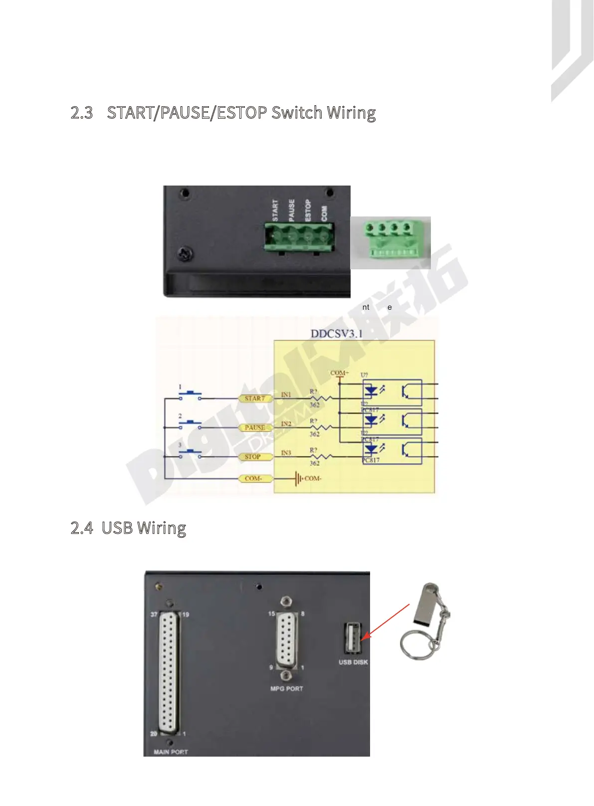
As Figure 2-3 shows, the power interface,there is a screw termimal for connection. The
marks are the “START”/”PAUSE”/”ESTOP” and “COM” for external switches. And Figure 2-4 is
the circuit drawing for the connection.The “Start” and “Pause” can be defined as other func-
tions.Detailed information please refers to #446 and #447 in Param Page.
2.3 START/PAUSE/ESTOP Switch Wiring
This USB port is the standard USB A-type. A 50cm USB extension cord with installation plug
is supplied with the controller. See the diagram Figure 2-5 for reference.
2.4 USB Wiring
Figure 2-4 Circuit drawing of START/PAUSE/ESTOP/COM
Figure 2-5 USB interface
Figure 2-3 START/PAUSE/ESTOP/COM interface
As the Figure shows, the wiring section of the controller has Input Ports,Spindle&Output
Ports,stepper/Servo control step and direction output,MPG Port, USB Port and Power supply
Port.
 Loading...


