Page -18Digital Dream Standalone Motion Controller DDCS V3.1 DDCS V3.1 Users Manual
2.6.3 Stepper/Servo Control Output
The stepper/servo control output,we cite differential Pulse and Direction output method,Max.
500Khz per axis.DDCS V3.1 there is 3 or 4 axis for option
PIN 18 (AD-),PIN 36 (AD+),PIN 17 (AP-),PIN 35 (AP+) is A Axis Control Output Pins;
AD- means the Direction signal negative output for A axis,AP+ means the Direction signal posi-
tive output for A axis,AP- means the Pulse signal negative output,AP+ means the Pluse Signal posi-
tive output.
The Pulse and Direction signal output voltage is ±5V.
PIN 18(AD-),PIN 36 (AD+),PIN 17 (AP-),PIN 35 (AP+) is A Axis Control Output Pins;
PIN 16 (ZD-),PIN 34 (ZD+),PIN 15 (ZP-),PIN 33 (ZP+) is Z Axis Control Output Pins;
PIN 14 (YD-),PIN 32 (YD+),PIN 13 (YP-),PIN 31 (YP+) is Y Axis Control Output Pins;
PIN 12 (XD-),PIN 30 (XD+),PIN 11 (XP-),PIN 29 (XP+) is X Axis Control Output Pins.
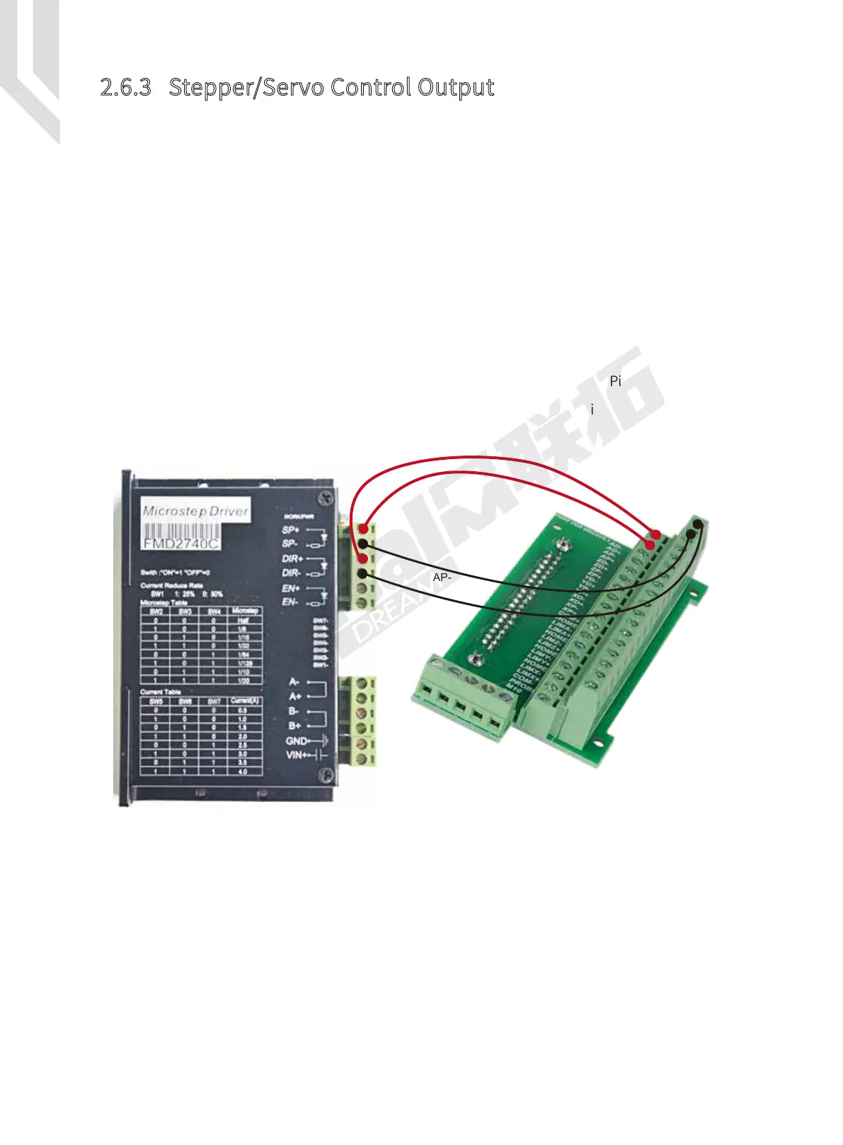
The following Figure 2-16 is the example of stepper driver wiring as A axis.
AD-
AP-
AD+
AP+
Figure 2-16 The Stepper driver wiring as A Axis
 Loading...


