Page -12Digital Dream Standalone Motion Controller DDCS V3.1 DDCS V3.1 Users Manual
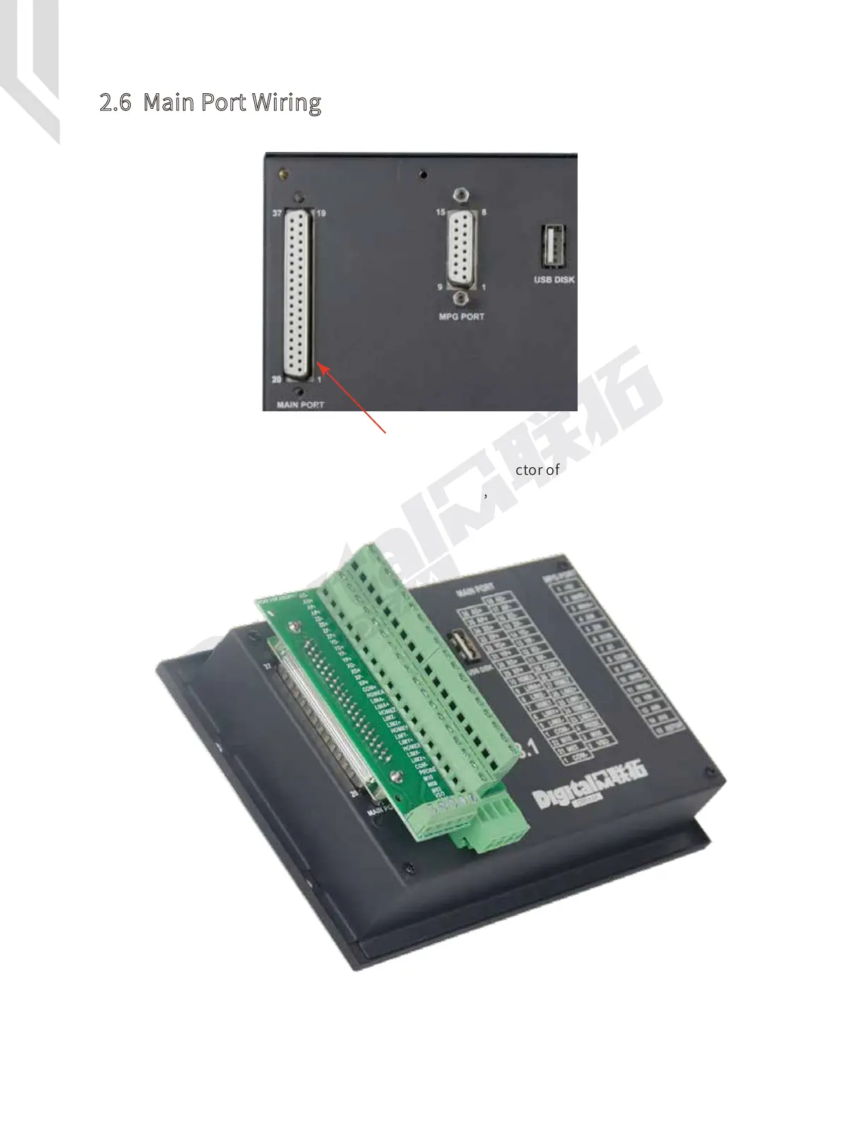
Figure 2-7 shows the main port position:
We supply a wiring terminal to fit the 37 pin female connector of the main port. This simpli-
fies the wiring. Please note in Figure 2.8, at the 4 corners, there are screws to lock the terminal
to the controller.
2.6 Main Port Wiring
Figure 2-7 Main Port
Figure 2-8 Main Port with wiring terminal
 Loading...


