Page -15
Digital Dream Standalone Motion Controller DDCS V3.1 DDCS V3.1 Users Manual
PIN3(M8),PIN22(M10),PIN2(VSO) and PIN21(M3) is for spindle control output.The spindle
control output terminal offers connections for Start and Stop of the Spindle (M3/M5), Start/Stop
of Cooling (M8/M9) and Start/Stop of Lubrication (M10/M11). These three output terminals are
signals open to ground. The highest electric current can be absorbed is 50mA. The speed
controlling output terminal can output 0-10V. It can adjust the speed of the spindle motor by
sending the voltage between 0 and 10V to the VFD according the the Spindle Speed Setting.
Controlling the speed of a spindle with a VFD (variable frequency drive) only needs the
Start/Stop signal and the 0-10V signal to control the frequency.
The following table 2-6 shows the wiring with Sunfar VFD:
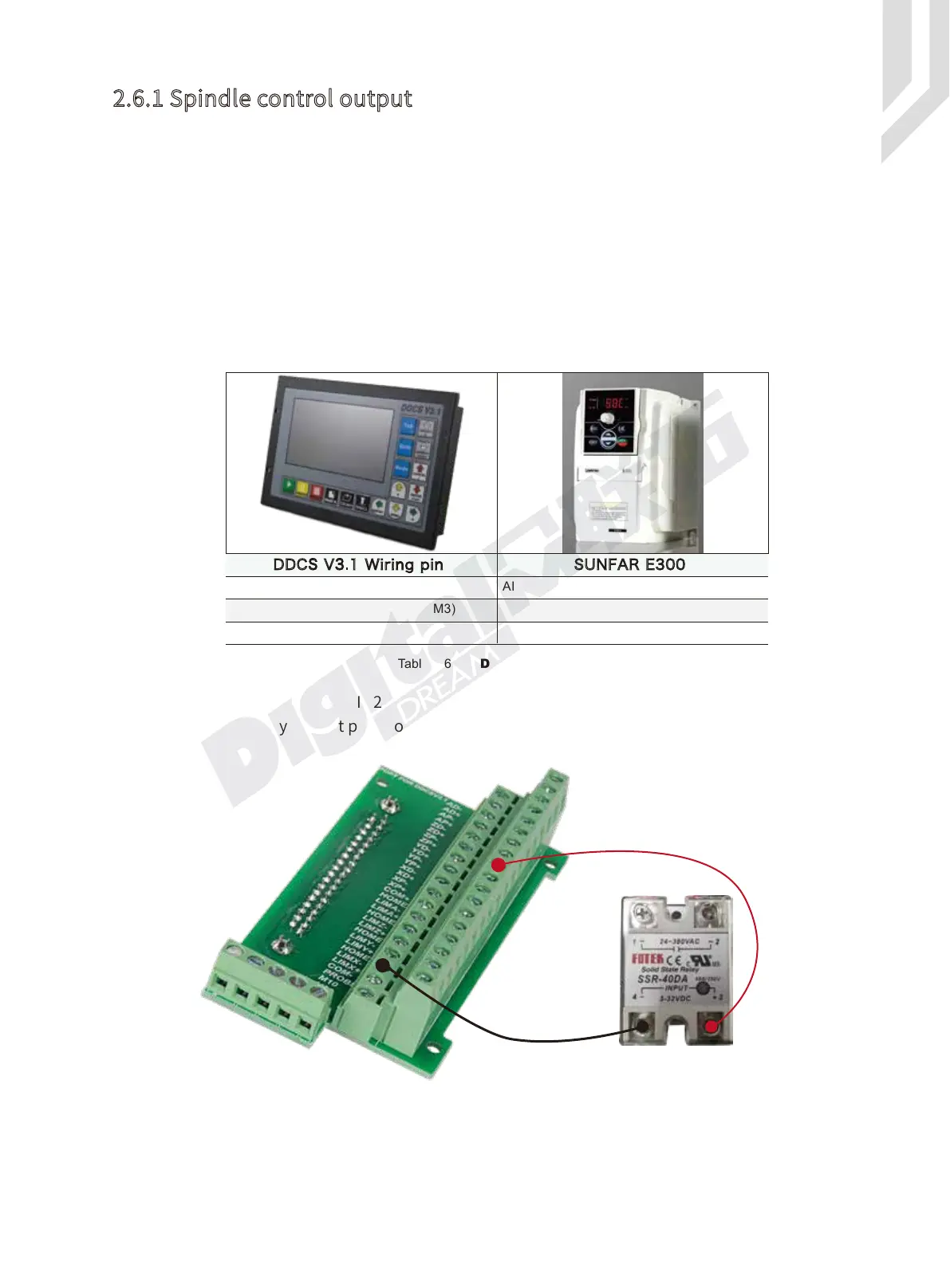
PIN3(M8),PIN22(M10) and PIN21(M3) is also can be used for OUTPUT ports.For example,it
can be used for a Relay output port.For example the Figure 2-10 shows the wiring methods:
2.6.1 Spindle control output
Figure 2-10 Wiring Methods with Relay
DDCS V3.1 Wiring pin SUNFAR E300
AI
FWD
CM
Speed output(0-10V)PIN2(VSO)
Start and stop of spindle PIN21(M3)
Output ground
Table 2-6 DDCS and VFD wiring
PIN20:COM+
PIN22:M10
 Loading...


