Digital Dream Standalone Motion Controller DDCS V3.1 DDCS V3.1 Users Manual Page -8
In general, the power supply of industrial control’s equipment products are complex. They
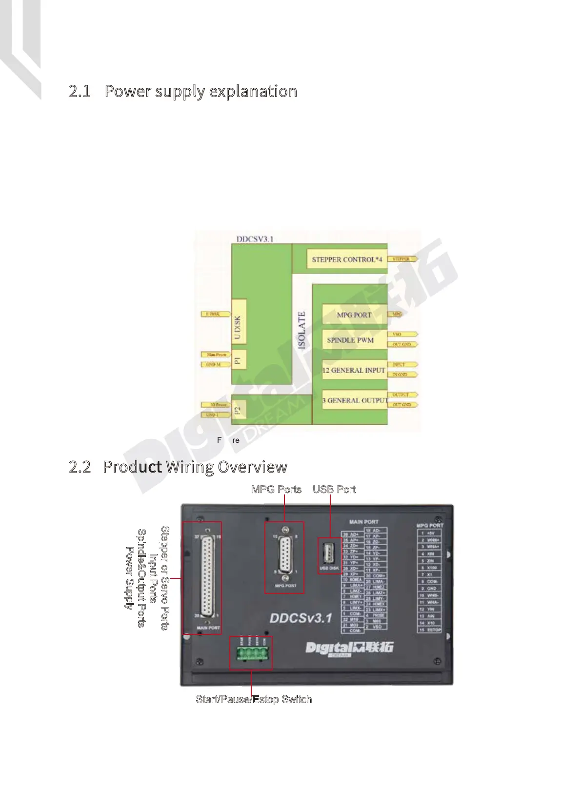
have many different ground levels. The internal power structure of this product is as follows:
See Figure 2-1. The Controller need two power supplies,Main power is for system,IO Power
is for IO ports.The Main Power input and USB stick and Stepper/Servo Control module share the
same ground.IO Power,MPG Port,Spindle PWM,12 Inputs and 3 Outputs share same ground,
between them which is optical isolation. As for the spindle port, take the output ground for
references and the 0-10V adjustable voltages to adjust the spindle speed (refer to spindle VFD
manual). The M3/M8/M10 digital output ports pull to ground.
Figure 2-1 Power supply System structure
2 Wiring
2.1 Power supply explanation
2.2 Product Wiring Overview
Figure 2-2 Wiring and Ports
MPG Ports
Start/Pause/Estop Switch
USB Port
Stepper or Servo Ports
Input Ports
Spindle&Output Ports
Power Supply

 Loading...


