Page -11Digital Dream Standalone Motion Controller DDCS V3.1 DDCS V3.1 Users Manual
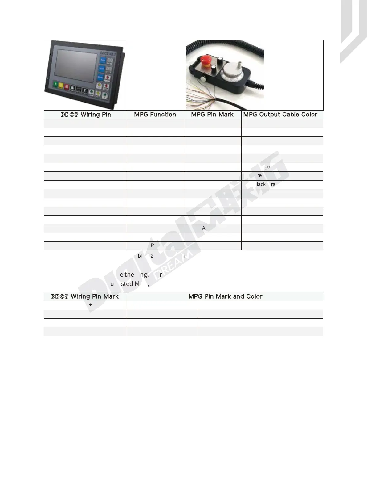
Table 2-2 DDCS Wiring with standard MPG
Table 2-3 DDCS Wiring with Single-terminal MPG
Note: It you want to use the single-terminal MPG (there is no A-B-MPG), please refer to table 2-3
for reference. As for the unlisted MPG, please take the differential MPG wiring mode.
DDCS Wiring Pin
Blue
X1 Grey
X10 Black/Grey
X100 Orange
X Yellow
Y Black/Yellow
Z
X1 Ratio
X100 Ratio
X Axis
Z Axis Brown
A Black/Brown
A+ Green
A- Purple
B+
B-
A Phase -
B Phase -
A Phase +
B Phase + White
Purple/Black
COMEnable Switch Black/Orange,Blue/Yellow
Black,Whilte/Black
Red, Green/BlackVcc(+5V)
ESTOP ESTOP
X10 Ratio
Y Axis
A Axis
ESTOP
X1
X10
X100
GND GNDPower Supply -
Power Supply +
WHB-
WHA-
+5V-W
X-IN
Y-IN
Z-IN
A-IN
WHB+
WHA+
WHB-
WHA-
WHB+
WHA+
COM-
MPG Function MPG Pin Mark MPG Output Cable Color
A+ Green
0V Black
B+ White
0V Black
DDCS Wiring Pin Mark MPG Pin Mark and Color
 Loading...


