Page -13
Digital Dream Standalone Motion Controller DDCS V3.1 DDCS V3.1 Users Manual
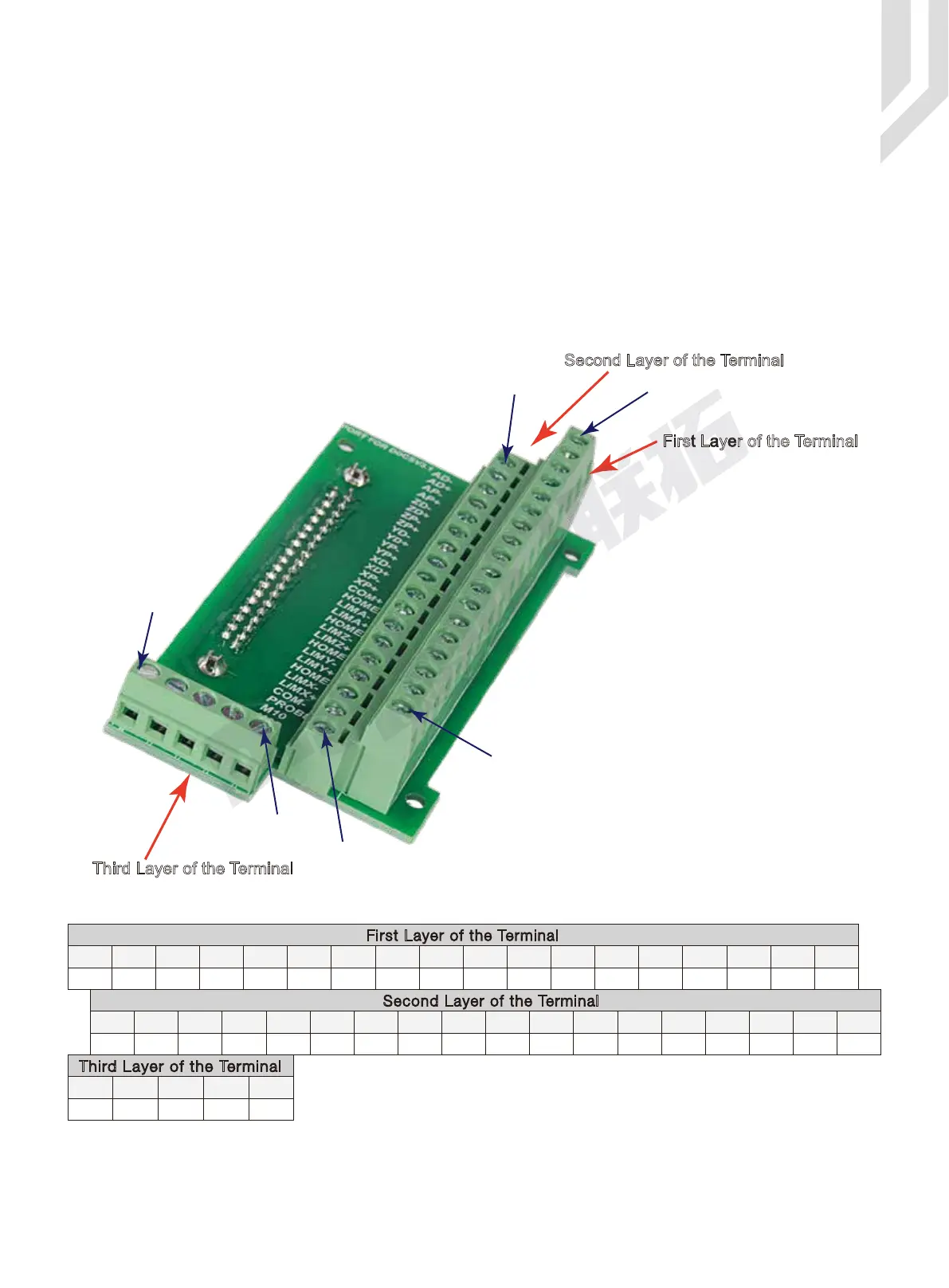
There are 3 rows of connectors on the terminal block. Please see Pic 2-9 which shows the
shows the pin allocation to each row. It supports the following interfaces:
1) Stepper/Servo Output Ports;
2) The Spindle Control Output Ports;
3) The E-stop,Limit,Home and Probe and other Inputs ports;
4) 24V DC Power Supply ports for the Controller;
5) 24V DC Power Supply ports for the I/O Unit.
For the connector to pin mapping please refer to Table 2-4:
Figure 2-9 3-Layers wiring terminal
First Layer of the Terminal
Pin 18:AD-
Pin 2:VSO
Pin 36:AD+
Pin 1:COM-
Pin 1:COM-
Pin 19:24V
Second Layer of the Terminal
Third Layer of the Terminal
Table 2-4 Main Port Pin No. and Mark
PIN 1 PIN 1
COM- COM-
PIN 23 PIN 3PIN 20
XL++ M8COM+ AL--
ZHOME
ZL++
XHOME
PROBE
PIN 28 PIN 27 PIN 26 PIN 24 PIN 4
PIN 18 PIN 17 PIN 16 PIN 15 PIN 14 PIN 13 PIN 12 PIN 11
AD- AP- ZD- ZP- YD- YP- XD- XP-
First Layer of the Terminal
PIN 25 PIN 2
YL-- VSO
GND24V COM+
PIN 37PIN 19 PIN 20
Third Layer of the Terminal
PIN 6
YL++
AL++
ZL--
YHOME
M3 COM-
PIN 9 PIN 8 PIN 7 PIN 21 PIN 1PIN 36 PIN 35 PIN 34 PIN 33 PIN 32 PIN 31 PIN 30 PIN 29 PIN 5 PIN 22PIN 1
AD+ AP+ ZD+ ZP+ YD+ YP+ XD+ XP+
XL-- M10COM-
Second Layer of the Terminal
AHOME
PIN 10
The Pin No. is DB37 interface Pin No.
 Loading...


