E-8
English
4
B2* Press switch brine
B3* Hot water thermostat
B4* Swimming pool water thermostat
E9 Flange heater for hot water
E10* Heat generator 2 (boiler or immersion heater)
F1 Control fuse N1 5x20 / 2.0 A slow-acting
F2 Load fuse for plug-in terminals J12 and J13 5 x 20 /
4.0 A slow-acting
F3 Load fuse for plug-in terminals J15 to J18 5 x 20 /
4.0 A slow-acting
H5* Remote fault indicator lamp
J1 Control unit power supply connection
(24 V AC / 50 Hz)
J2 Connection for hot water sensor, return flow sensor and
external sensor
J3 Input for HP code and flow sensor via
control line plug connector X8
J4 0-10 V DC output for controlling the frequency
converter, remote fault indicator, and swimming pool
circulating pump
J5 Connection for hot water thermostat, swimming pool
thermostat and utility block functions
J6 Connection for the heating circuit 2 sensor and defrost end
sensor
J7 Connection for “low-pressure brine” alarm message
J8 230 V AC input and outputs for controlling the HP
control line plug connector X11
J9 Socket not used
J10 Socket for connecting the remote control (6-pole)
J11 Connection not used
J12 to
J18 230 V AC outputs for controlling the system
components (pump, mixer, heating element, solenoid
valve, boiler)
K9 230 V/ 24 V coupling relay
K11* Electron. relay for remote fault indicator
K12* Electron. relay for swimming pool water circulating pump
K20* Contactor for heat exchanger 2
K21* Contactor for electrical flange heater for hot water
K22* Utility blocking contactor (EBC)
K23* Auxiliary relay for disable contactor (SPR)
M11* Primary pump
M13* Heat circulating pump
M15* Heat circulating pump of heating circuit 2
M16* Auxiliary circulating pump
M18* Hot water circulating pump
M19* Swimming pool water circulating pump
M21* Mixer for main circuit (bivalent system) or heating circuit 3
M22* Mixer for heating circuit 2
N1 Control unit
N10 Remote control
N11 Relay module
R1 External temperature sensor
R2 Return flow sensor
R3 Hot water sensor
R5 Sensor for heating circuit 2
R9 Flow sensor
R12 Defrost end sensor
R13 Sensor for heating circuit 3/bivalent-regenerative
T1 230 / 24 V AC / 28 VA safety transformer
X1 Terminal strip - supply connection, N and PE distribution
board
X2 24 V AC distribution board terminal
X3 Distribution board terminal - ground
X8 Control line plug connector (extra-low voltage)
X11 230 V AC control line plug connector
Abbreviations:
MA Mixer “OPEN”
MZ Mixer “CLOSED”
*) Components must be supplied by the customer
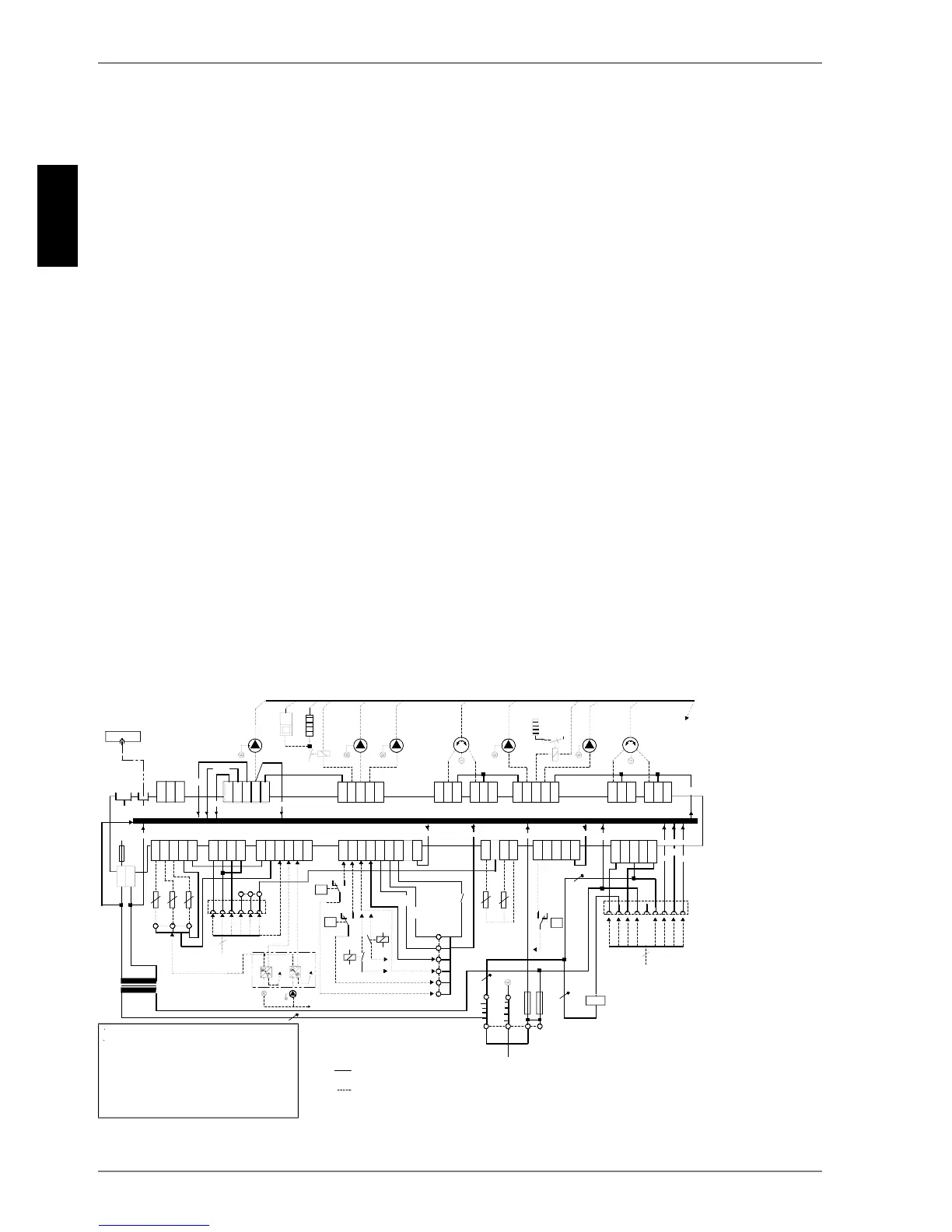
Fig. 4.2: Circuit diagram of the wall-mounted heat pump manager
,'
7
;
:S
5
9$&
9$&
9$&
7
9$&
;
5 5 5
&RG:3
*1'
7
(96
63
5
&
-
;
-
,'&
-
*
*
-
)
9a
$7
1
;*
-
%
%
%
%&
9'
&
*1'
%
*1'
-
;
)/
-
1
[[[[[
%
-
%&
<
9*
<
<
<
9*
-
12
12
12
;
&
-
,'
,'
,'
,'
,'
,'
&
12
-
12
12
&
(
+.
0
0
$7U
$7U
SRO
SRO
;
1
;
/3(
$
$
6W|
0
.
6W|
0
$
$
;
9$&
;
))
;
3
%
$
: S
9HU
.
$
1
/
1'
+'
$(
(*6
;
9HU
383
9HQ
0
=
0$
-
%
&
-* -*
$((*6
,'&
,'
9$&
-
12
&
12
&
-
%
-
,'
,'
,'
,'
*1'
%
-&
1&
&
-
&
12
12
12
0 0
0=
0$
-
&
,'&
-*
-
9$&
,'+
,'
,'&
,'
,'+
-&
-
12
1&
&
12
12
12
-!
12
1&
)/
0
;1
0
(
.
0
.
%
%
.
.
.
7
/
PD[
:
$
$
-&
0
-&
+
PD[
:
1
; 1
.
5
5
$$
/
7
$
$
5
;
&DUWRXFKHFKDXIIDQWHÂ
,PPHUVLRQKHDWHU
RGHUÂRUÂRX
+HL]VWDEÂ
6WHXHUOHLWXQJ
&RQWUROOLQH
/LJQHGHFRPPDQGH
6WHXHUOHLWXQJ
&RQWUROOLQH
/LJQHGHFRPPDQGH
$GHU1UÂ&RUH1RÂ$PHQ
1HW]Â0DLQVÂ5pVHDX
9$&+]
ZHUNVVHLWLJYHUGUDKWHW
:LUHGUHDG\IRUXVH
&kEOpHQXVLQH
EDXVHLWVQDFK%HGDUIDQ]XVFKOLHHQ
PXVWEHVXSSOLHGE\FXVWRPHUWREHFRQQHFWHGDVUHTXLUHG
$UDFFRUGHUVLEHVRLQHVWSDUOHSURSULpWDLUH
(96635!.RQWDNWRIIHQ 6SHUUH
8WLOLW\FRPSDQ\EORFN!FRQWDFWRSHQ EORFN
(96635!FRQWDFWRXYHUW EORFDJH
$FKWXQJ
-ELV-VRZLH;;XQG;OLHJHQDQ9
(VGDUINHLQH1HW]VSDQQXQJDQJHOHJWZHUGHQ
:DUQLQJ
-WR-DVZHOODV;;DQG;DUHFRQQHFWHGWR9
'RQRWFRQQHFWWRPDLQVYROWDJH
$WWHQWLRQ
-j-DLQVLTXH;;HW;VRQWVXU9
1HSDVDSSOLTXHUGHWHQVLRQVHFWHXU